Hi All
I've been posting on another forum but not getting much traction there. I'm pretty new to this but willing to learn - so don't hold back!
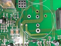
I have an Arcam P7. It's a seven channel power amp with a bunch of amplifiers on their own cards. It was humming from the speakers pretty badly and the sound has become pretty unimpressive. Dull, muted etc. I opened the unit up and saw that the capacitors were all bulging. Assuming this was a clear fault I have ordered replacements and de-soldered two from one board. And this is where my first challenge is, I lifted the top, component side pad. The other side of the board is ok, which is the side I solder the capacitor legs to. I was going to just solder the replacement capacitors in place but thought I should pause and ask for help.
My question is how to deal with this. Do I need to replace the top pad? If so would copper tape work or should I take a wire from the other side of the board. Also - what do I call either side of the board - I'm conscious of the fact that I don't know the right terminology.
I am working with a hake FR301. I think I screwed up by using the wrong size tip and applying too much heat. I now have the 1.6mm that fits the capacitor legs ok.
I've been posting on another forum but not getting much traction there. I'm pretty new to this but willing to learn - so don't hold back!
I have an Arcam P7. It's a seven channel power amp with a bunch of amplifiers on their own cards. It was humming from the speakers pretty badly and the sound has become pretty unimpressive. Dull, muted etc. I opened the unit up and saw that the capacitors were all bulging. Assuming this was a clear fault I have ordered replacements and de-soldered two from one board. And this is where my first challenge is, I lifted the top, component side pad. The other side of the board is ok, which is the side I solder the capacitor legs to. I was going to just solder the replacement capacitors in place but thought I should pause and ask for help.
My question is how to deal with this. Do I need to replace the top pad? If so would copper tape work or should I take a wire from the other side of the board. Also - what do I call either side of the board - I'm conscious of the fact that I don't know the right terminology.
I am working with a hake FR301. I think I screwed up by using the wrong size tip and applying too much heat. I now have the 1.6mm that fits the capacitor legs ok.
Attachments
Clean PCB with acetone, use a super glue to stick back the track in place.
Or use thin wire, and bend it along the original pattern, solder at the break, and to the component. Remove the broken foil which has come off the board.
Can use epoxy, just use abrasive to remove residue after sticking in both cases.
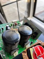
What make are those caps?
Change those of the same make throughout the amp.
Could be bad quality, or defective batch.
Or use thin wire, and bend it along the original pattern, solder at the break, and to the component. Remove the broken foil which has come off the board.
Can use epoxy, just use abrasive to remove residue after sticking in both cases.
What make are those caps?
Change those of the same make throughout the amp.
Could be bad quality, or defective batch.
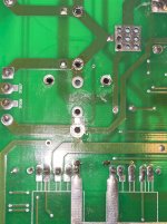
If there is no trace connected to the side with the lifted pad you are ok. if there was a connection to the pad you have to put a jumper wire, match the gauge with the width of the trace from the leg on the cap to wherever the trace leads to. You are essentially making a new path. You must still solder the cap so that the solder flows through the hole Andries the leg to the pad n te other side. Don’t flood the solder in,just enough to make a connection with the pad. When you are unsoldering the next ones use a solder wick or sucker to get the solder out of the hole. If the pad on the component side comes off your iron is too cold, if it is on the other side you are too hot causing the pad to delaminate. Good luck and go slow!
Sometimes I use a heated steel needle to clear holes.
Use flux to melt the solder if needed, and remove residues, it is corrosive.
Use flux to melt the solder if needed, and remove residues, it is corrosive.
Just took a better look at your issue and the only pads that are actually important are the ones that makeup the long part of the cross. The two On the short axis are there for stability and not actually connected. Just put in jumpers from the cap to the nearest point on the same trace.
Yes, the pad for the positive terminal on the top of the board lifted. The capacitor leg solders onto the other side of the board and track is still there. But - is this a dual layer board with a through hole pad? I don't see a clear track on the board leading to this so wondering if I even need to fix the top pad? I haven't worked with any boards like this before so I'm still trying to learn how to handle them.
You dont need to fix the top pad. Just make a good solid connection on the bottom. I would probably secure the capacitors in place afterward with hotmelt glue to ease the stress on the solder connections
After even more looking the pads on the top of the board do nothing! Just put the new caps in and solder them well. That should do it.
Try and find Japanese, or Vishay, should be cheaper.
Sometimes 80 is non standard, 100V may be cheaper.
https://www.mouser.in/ProductDetail...f0viD3Y3fHxNcSaiftwB88Ar/beM%2BN7O5Xb3ZiWZA==
Might be cheaper in your area.
Sometimes 80 is non standard, 100V may be cheaper.
https://www.mouser.in/ProductDetail...f0viD3Y3fHxNcSaiftwB88Ar/beM%2BN7O5Xb3ZiWZA==
Might be cheaper in your area.
It was fairly usual for the plastic top caps to bulge on the Samwha capacitors - this doesn't necessarily mean they are leaking. The amplifier runs fairly warm and the top bungs/caps start to warp but don't actually leak electrolyte. This was checked by Samwha in the first production run, and I recall them checking the internals of the cap by x-ray, and confirming it was just the top bungs warping.Hi All
I've been posting on another forum but not getting much traction there. I'm pretty new to this but willing to learn - so don't hold back!
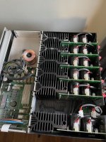
I have an Arcam P7. It's a seven channel power amp with a bunch of amplifiers on their own cards. It was humming from the speakers pretty badly and the sound has become pretty unimpressive. Dull, muted etc. I opened the unit up and saw that the capacitors were all bulging. Assuming this was a clear fault I have ordered replacements and de-soldered two from one board. And this is where my first challenge is, I lifted the top, component side pad. The other side of the board is ok, which is the side I solder the capacitor legs to. I was going to just solder the replacement capacitors in place but thought I should pause and ask for help.
My question is how to deal with this. Do I need to replace the top pad? If so would copper tape work or should I take a wire from the other side of the board. Also - what do I call either side of the board - I'm conscious of the fact that I don't know the right terminology.
I am working with a hake FR301. I think I screwed up by using the wrong size tip and applying too much heat. I now have the 1.6mm that fits the capacitor legs ok.
The P7 has 7 independent power boards with their own rectifiers and smoothing caps, and it would be very unusual for all 7 channels to be humming. I would check the bias for each amplifier on the test point gold pins at the top of each board - it should be around 16mv after around 10-15 minutes after switch on from cold. If the amp hasn't been very well ventilated in it's lifetime, then these bias pots start to fail and the bias will go up - all the pots (7) need to be replaced and the bias set to 16mv when stable.
Poor sound quality results if the contacts for the loudspeaker protection relays are degraded - it is recommended to replace all 7 relays on the power amp boards. Hope this helps!
Yes - very helpful indeed. Thank you! I think you're right about the capacitors and I had the same feedback on another forum. I started replacing them already so I'll just go ahead and do them all anyway now.
I will check bias next. Is there anyway to test the relay itself?
I will check bias next. Is there anyway to test the relay itself?
Normally you would measure across the contacts and check for resistance change when you mute/unmute the channel, but this isn't possible as you can't access those points easily, and there isn't a mute switch. The usual audible signs are slight distortion or hard edge to the sound that is intermittent in nature, or slight changes in level. A possible way to check would be to play a 1khz tone through one channel at a time, at a low level, and listen through a loudspeaker while tapping the board with your finger and listening for changes in level or distortion. Relay part details are Omron G2R-1A-E and they are available from RS Components.Yes - very helpful indeed. Thank you! I think you're right about the capacitors and I had the same feedback on another forum. I started replacing them already so I'll just go ahead and do them all anyway now.
I will check bias next. Is there anyway to test the relay itself?
While you have all the boards out it might be a good idea to check R104 (surface mount) ground lift resistor on each board, for 100 ohms, as these sometimes go open circuit and cause possible hum problems.
From your pix that pad is barely affected TBH.
Use a round toothpick to clear thru holes heat solder then gently push the toothpick through.
Sadly Arcams are fairly low grade quality. Lots of relay/ switch and mediocre sound issues with that brand.
Good luck.
Use a round toothpick to clear thru holes heat solder then gently push the toothpick through.
Sadly Arcams are fairly low grade quality. Lots of relay/ switch and mediocre sound issues with that brand.
Good luck.
Sewing needles, and long steel pins work, stronger than wood.
Solder does not stick to steel, if it is smooth.
Solder does not stick to steel, if it is smooth.
I replaced the relays. Reset the bias which was needed but not off the scale and the pots are stable so I left them in place. I reflowed all the speaker outputs on the board as they looked questionable. That seems to have done it. Sounds fantastic again and the buzzing seems gone. Thanks again for your generous help.Normally you would measure across the contacts and check for resistance change when you mute/unmute the channel, but this isn't possible as you can't access those points easily, and there isn't a mute switch. The usual audible signs are slight distortion or hard edge to the sound that is intermittent in nature, or slight changes in level. A possible way to check would be to play a 1khz tone through one channel at a time, at a low level, and listen through a loudspeaker while tapping the board with your finger and listening for changes in level or distortion. Relay part details are Omron G2R-1A-E and they are available from RS Components.
While you have all the boards out it might be a good idea to check R104 (surface mount) ground lift resistor on each board, for 100 ohms, as these sometimes go open circuit and cause possible hum problems.
I'm glad to be of some help, and that you are now enjoying the great and powerful sound of the P7!I replaced the relays. Reset the bias which was needed but not off the scale and the pots are stable so I left them in place. I reflowed all the speaker outputs on the board as they looked questionable. That seems to have done it. Sounds fantastic again and the buzzing seems gone. Thanks again for your generous help.
- Home
- Amplifiers
- Solid State
- Lifted Pad on Arcam P7