Hi
I just built, what I was thinking to be, a very simple dual 5v linear regulated power supply, to power a rpi-4 and a hat with a digital audio out. I'm running ropieeXL.
The transformer is rated 230v to 2x24v 30VA ( https://www.audiophonics.fr/en/toroidal-transformers/toroidal-transformer-30va-2x24v-p-5649.html ) feeding two LT1084 1.2V / 19.5V 2.5A regulated linear power supply modules ( https://www.audiophonics.fr/en/diy-...th-heat-slug-lt1084-12v-195v-25a-p-11645.html ).
I measured the voltage AC out of the transformer is 24v on both secondery outs, and the output voltage out of the linear power supply module is 5,01v and 5,03v DC on each side. The rpi-4 and the hat lights turn on when I power everything but nothing happen, the rpi-4 lights blink as usual but ropiee never realy starts up, so I checked the current being send to the Board and I get 0.035 amps which may explain why it's not working at all. Voltage still read 5v.
I can't understand why this is happening... is it possible that I wired something wrong ? The boards work because I just connected them to a cheap switch power supply and I can run rupiee and stream music with no issues at all.
I admit I'm totally newbie and probably shouldn't be playing with power supplies, it can really be user error, but I would really appreciate some help 🙂
Thx in advance
Nuno
Last edited:
Please start by thinking why you used 2 x 24V. BTW Volts is with a capital V. It is about a PSU that needs to regulate to 5V. You would need a 1 x 7V transformer at most. Or 2 x 7V in parallel. The RPi 4 normally needs a 3A PSU. It would then make sense to go for 5V 3A and a margin so let's say we choose a 4A transformer. You need a 5V 4A so 20W PSU created with a 7V 4A so 30 VA transformer. A standard 50VA version certainly won't hurt when using 2 regulators 5V 2.5A.
Askers never have time and we need to solve their things ASAP but askers must give enough information. This in the form of pictures.
Askers never have time and we need to solve their things ASAP but askers must give enough information. This in the form of pictures.
Last edited:
Please start by thinking why you used 2 x 24V. BTW Volts is with a capital V. It is about a PSU that needs to regulate to 5V. You would need a 1 x 7V transformer at most. Or 2 x 7V in parallel. The RPi 4 normally needs a 3A PSU. It would then make sense to go for 5V 3A and a margin so let's say we choose a 4A transformer. You need a 5V 4A so 20W PSU created with a 7V 4A so 30 VA transformer. A standard 50VA version certainly won't hurt when using 2 regulators 5V 2.5A.
Askers never have time and we need to solve their things ASAP but askers must give enough information. This in the form of pictures.
Hi Jean-Paul
The reason for the 24V output transforner is because the hat that I'm using, pi2aes link below, can be powered with 19V to 36V and it will step down the voltage and feed the board 5V and 5V to the pi-4 throught GPIO.
https://www.pi2design.com/store/p19/PI2AES_-_PRO_AUDIO_SHIELD.html
Alternatively I can power both boards separately using two pins available in the pi2aes board marked as 5V, and separately feed 5V to the pi-4. I have been using this option with a cheap switch power supply for several months.
I wanted to compare how both options a) 5V separately feed to both boards or b) feeding around 24V to the Pi2aes board and let it step-down the voltage and feed the pi-4 and pick up which one sounds best so this is why I picked up this transformer and power supply module.
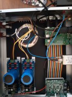
Let me attach some pics.
Maybe this threat will help other newbies in the future, I should have asked questions before starting putting this together but I always try ti investigate as much as possible in advance but I see my research wasn't sufficient as I'm having troubles.
Thx
Regards, Nuno
Attachments


No one would have known that you use device X as it was not mentioned at all. Device X is the exception with specific requirements (I hope you see the trap of using jargon and fancy names of devices and designers) like 19 to 36V at an unknown current so first make stuff OK regarding the more or less standard RPi PSU requirements and then design a separate PSU for device X.
The focus should then be to find out what current device X with 19 to 36V voltage limits would consume, then an adequate PSU can be designed. It is even better to speak of "the load" with a voltage and current requirement.
Please read carefully: the design error is to use a too high voltage because of just 1 device X that probably takes little power and to use the same high voltages for relatively high power demands in the 5V area. This results in a lot of useless heat and power loss. Not green at all. P = U x I. Unprecise but in the case of 24 x 1.41 you'll have 34V. 34 - 5 = 29. With just 1A load current you'll have 29 x 1 = 29 W of useless heat!!!!!!!! Totally unrealistic and the regulators won't like it and you need a very large heatsink too. You'll be the guy then point at when global warming is discussed 🙂 Let's exxagerate as we like that. A 7V 50VA transformer is bought. 7 x 1.41 = 9.87. 9.87 - 5 = 3.87. 3.87 x 1 (Ampere)= 3.87 Watt in heat/power loss. You see?! That is 25W less gone to heat.
It will not come as a surprise you probably need a separate 18...20V xA xx VA transformer for device X (assuming device X is low power). So, 20 x 1.41 = 28.2V. With a modern low drop linear regulator you can regulate this to 20 to 22V easily. Pleased do the imprecise calculation yourself what will happen with a 22V, a 25V and a 30V transformer. You can assume 0.5A just for the calculation.
*I have to point at the uninsulated faston connectors which you definitely will regret one day. Please adapt to the insulated version as they are way more safe.
Last edited:
No one would have known that you use device X as it was not mentioned at all. Device X is the exception with specific requirements (I hope you see the trap of using jargon and fancy names of devices and designers) like 19 to 36V at an unknown current so first make stuff OK regarding the more or less standard RPi PSU requirements and then design a separate PSU for device X.
The focus should then be to find out what current device X with 19 to 36V voltage limits would consume, then an adequate PSU can be designed.
Please read carefully: the design error is to use a too high voltage because of just 1 device X that probably takes little power and to use the same high voltages for relatively high power demands in the 5V area. This results in a lot of useless heat and power loss. Not green at all. P = U x I. Unprecise but in the case of 24 x 1.41 you'll have 34V. 34 - 5 = 29. With just 1A load current you'll have 29 x 1 = 29 W of useless heat!!!!!!!! Totally unrealistic and the regulators won't like it and you need a very large heatsink too. You'll be the guy then point at when global warming is discussed 🙂 Let's exxagerate as we like that. A 7V 50VA transformer is bought. 7 x 1.41 = 9.87. 9.87 - 5 = 3.87. 3.87 x 1 (Ampere)= 3.87 Watt in heat/power loss. You see?! That is 25W less gone to heat.
It will not come as a surprise you probably need a separate 18...20V xA xx VA transformer for device X (assuming device X is low power). So, 18 x 1.41 = 25.4V. With a modern linear regulator you can regulate this to 19V easily.
*I have to point at the uninsulated faston connectors which you definitely will regret one day. Please adapt to the insulated version as they are way more safe.
Hi Jean-Paul
Yes... I didnt explain it all and sorry for that. What I couldn't understand is the current part so this is why I only focussed on that part of the question.
Here is what I tried:
Connect only the pi-4, unplugging the pi2aes - not working, voltage (5V) is fine but no sufficient current.
Connecting the pi2aes with 19V and leting it power the pi-4, voltage is fine but both units don't power up properly as explained before.
Disconnect all, and plugged my old 19V switching power supply and powered the Pi2aes and all is working. (Which is what I have been using)
Powered both boards with 5V separately from 2 simple phone charges and works perfectly too.
So you see why I'm puzzled ?
Thx for the clarification of inefficiency, I was trying to go with two solutions, lower voltage separately powering the boards vs higher voltage to one single board where I would need the 19V minimum. I can't make wither work, actually the 5V + 5V worked for a few minutes, I got music but after stopped (literally a few minutes, didn't run for more then just a few songs), once again what changed wasn't voltage output but the current.
I'm puzzled, maybe something short out ...
Thx
PS: thx for the tip on the faston connectors, I will replace those if I can make this work, otherwise I will stop my adventure and get a pre built linear power supply. 😫
Hi I speak a different language and tried to explain carefully what is going on. You focus on 1 aspect and that is why things do not work out. You could reread things and you could try out the only good solution which is a lower voltage transformer like a standard 2 x 7V for the 2 x 5V your setup needs anyway. Like the Talema Nuvotem 61080 with 2 x 7V 50VA....If you live in a 115V area then look up the 115V version yourself. Since the basis is wrong I don't read all the information as it is not relevant as long as the main issue is not solved. Since it will never work out OK with 2 x 24V first solve that. Such high voltage differences only work out OK with switchers and not with linear PSU's!
It is simple: you have 2 loads of which 2 are 5V 3A max. (?) and possible extra load is 19 ...36V at ? current. If you look at challenges this way they may not be puzzling at all. With a little help from mister Ohm and P = U x I you can get quite far.
If you try to speak in terms of loads and how many and what they need things would be clear quite fast. The device X seems off with the 19...36V requirements in an almost exclusively 5V area but so be it.
BTW why is a switch used to one of the 2 linear PSU's? You would only need a mains switch and both PSUs to start simultaneously.
Last edited:
Rephrase: "you have 2 loads of which 2 are 5V 3A max. (?) or a single 5V 3A load and an odd load of 19 ...36V at ? current". That means a 2 x 7V 50VA transformer with either the windings used separately for scenario A or in parallel for scenario B. For scenario B the existing 2 x 24V toroid could be used with 2 windings in parallel feeding one of the 2 existing linear PSU's adjusted to 25V for the PI2EAS.
So that is what I can recommend, off to do something for myself. Ciao!
So that is what I can recommend, off to do something for myself. Ciao!
Rephrase: "you have 2 loads of which 2 are 5V 3A max. (?) or a single 5V 3A load and an odd load of 19 ...36V at ? current"
Hi Jean-Paul
English is not my native language too so we are on the same boat on this.
Probably I'm no clear and I apologise in advance, I don't want to power 3 components again the same time, I'm experimenting different combinations until I go after the one with better sound quality and only after I go for optimization of power, which is also important.
In a nutshell, here is all I tried
a) 1 component only to be powered by the linear power supply ( the rpi4) at 5V output measured by me (needing around 2A). Lights turn on but the pi4 didn't work at all, doesn't start up.
b) 1 component only to be powered by the linear power supply ( the pi2aes) at 5V (needing around 1A) and I powered the rpi4 with the old switching power supply separately to be sure. Rpi4 worked with no issues, pi2aes, that is connected to the linear power supply didn't, lights up but doesn't play music. I measures the current output to the pi2aes and got 0,035A ! that is far from sufficient.
c) I tried connecting the pi2aes with 19V using the recommended connection, not the pins workaround mentioned in b) and the pi2aes steps the power down to 5V and feed also 5V to the pi4 through the GPIO, didn't work, lights turn on but no operations. I tried this with a switch power supply I have and no issues, all works.
In all cases the voltage is there but not the current.
What worked for a couple of songs, which was my first configuration, was pi2aes 5V directly to the 5V pin input in the board and 5V to the pi4 thought USB C, using two power suply modules and the same 24V transformer with 2 secondary outputs connected separately to each power supply module. After a few songs it stopped working. I didn't measure current before (only measured voltage) but when it stopped working, only 10 minutes later after the first time I powered it on, this is when I measured the ridiculous low current output of 0,035A and started testing the cases a) b) c) to see if other configurations would work and also to check if the boards got damaged. Pi4 and pi2aes work perfectly, just can't get sufficient current from both linear power supply modules (I tried both together or both separately...).
This is what puzzle me, why it worked s few minutes and stopped and why the current output is so low that I can't power anything with the power supply.
One more note, I measured the voltage out of each secondary connections of the transformer and I get 24V on each, no issues.
I would really like to avoid returning the power supply and transformer before I understand if this is a defect or an user error, and a user error is very possible. Returning goods is no very ecco friendly either 🙂
Merci
Thx
Nuno
That's a give away. First, understand that it is not 'insufficient current' supplied by the supply. It is insufficient current draw by your Rpi etc.voltage (5V) is fine but no sufficient current.
If the supply was somehow current limited it would collapse far below 5V, which it doesn't.
So why does the Rpi etc draw insufficient current? My guess is that you believe that 5V is supplied but that the 5V is not present at all parts, so it won't work (and draws 'insufficient current'). It's easy to oversee something when swapping supply connectors/pins.
A good move wood be to check all points on the Rpi etc where you expect 5V and see that it is actually there. Also check that all ground points are actually grounded.
Jan
If your transformer is 2x24V 30VA how much current do you expect either secondary will provide at 5V after regulation?In a nutshell, here is all I tried
a) 1 component only to be powered by the linear power supply ( the rpi4) at 5V output measured by me (needing around 2A). Lights turn on but the pi4 didn't work at all, doesn't start up.
b) 1 component only to be powered by the linear power supply ( the pi2aes) at 5V (needing around 1A) and I powered the rpi4 with the old switching power supply separately to be sure. Rpi4 worked with no issues, pi2aes, that is connected to the linear power supply didn't, lights up but doesn't play music. I measures the current output to the pi2aes and got 0,035A ! that is far from sufficient.
c) I tried connecting the pi2aes with 19V using the recommended connection, not the pins workaround mentioned in b) and the pi2aes steps the power down to 5V and feed also 5V to the pi4 through the GPIO, didn't work, lights turn on but no operations. I tried this with a switch power supply I have and no issues, all works.
That's a give away. First, understand that it is not 'insufficient current' supplied by the supply. It is insufficient current draw by your Rpi etc.
If the supply was somehow current limited it would collapse far below 5V, which it doesn't.
So why does the Rpi etc draw insufficient current? My guess is that you believe that 5V is supplied but that the 5V is not present at all parts, so it won't work (and draws 'insufficient current'). It's easy to oversee something when swapping supply connectors/pins.
A good move wood be to check all points on the Rpi etc where you expect 5V and see that it is actually there. Also check that all ground points are actually grounded.
Jan
Hi Jan
Thx for the suggestion, indeed I didn't measure the pi4 I only measured the power supply output. Actually the rpi4 is working fine connected to the original power supply that it came with, or connected to my phone charger, I'm actually using it now connected with the phone charger and music has been playing for a couple of albuns already and no issues at all. So I was running this issue out. Does it make sense ?
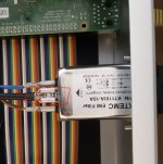
but you raise a point on ground, I have only one ground point connected to the case (see picture) which is the one coming from the IEC connector. Did I miss other ground connections ? The power supply modules have small plastic PVC spacers but are screwed to the bottom of case. The front and rear panel of the case are made of aluminium, bottom top and sides are steel.
Thx Nuno
Attachments
If your transformer is 2x24V 30VA how much current do you expect either secondary will provide at 5V after regulation?
I was expecting 2A out of 5V. Would that be possible ?
Not with that transformer. 2x24V 30VA gives about 630mA@24V on both secondaries without any losses. Regulating to 5V does not increase current. So max current at 5V is about 1.2A if you parallel the secondaries.
so maybe that is the reason
in my mind I would get 2.5A but maybe I read the specs of one transformer and ordered the wrong one.... could be...
But still strange that it worked for a few minutes, don't you think? 🤔
in my mind I would get 2.5A but maybe I read the specs of one transformer and ordered the wrong one.... could be...
But still strange that it worked for a few minutes, don't you think? 🤔
https://www.analog.com/media/en/technical-documentation/data-sheets/108345fh.pdf
Please look up maximum input-output voltage differential and also think what happens at power on sequence. And if I had known the 2 x 24V toroid is only 30VA I would have stopped commenting 😀 P = U x I, always. That transformer is too high in voltage and way too low in current. We techs call that a wrong transformer (for various reasons as explained).
Memorize that power is the product of voltage and current. P = U x I
Last edited:
Thx Jean-Paul
This is what happen when you don't want to ask in foruns before ordering stuff, I must have cross red the specs of the transformer as I was looking into different ones.
i hope I learned something, so a 50VA 2x7V would give me around 3,57A, am I correct ?

This is what happen when you don't want to ask in foruns before ordering stuff, I must have cross red the specs of the transformer as I was looking into different ones.
i hope I learned something, so a 50VA 2x7V would give me around 3,57A, am I correct ?
I double checked the specs on the 1084. With a Vin/Vout of 25V, which is roughly what you have, the 1084 is limited to a typ current of .6A. Not surprising, at that voltage difference it is the thermal that is going to be the limit. I am thinking the pi may start the boot process and then go undervoltage and not complete. Then the pi goes idle (but LED is still on) consuming much less current and bringing the 5V rail back up again. You'd pretty much need a scope to verify that on the 5V line. You could go to a dc/dc switcher which would magically get you more current. Not sure what a pi-4 requires as a min, but I have used a sanken br300 to power pi-3's using a 20VDC input. The BR max input is 30V, so your 24VAC is still too high. There must be other dc/dc switchers out there that could go to 40VDC as the input, which is about where I'd want to be with that transformer.

Yes that is correct but the rule of thumb (can also be calculated if you wish 🙂) is to take a factor 0.8 into account when rectifying and filtering. So it will be 2.85A per winding so per 7V output continuously which hopefully won't be like that. Also... if you load one winding with only half the current then the other is able to output a little more. The total maximum continuous load will however be 50VA x 0.8 so 40VA. Knowing that the original switcher for RPi is 5V 3A so 15VA we can assume we are on the safe side with 5V 20VA per PSU.Thx Jean-Paul
This is what happen when you don't want to ask in foruns before ordering stuff, I must have cross red the specs of the transformer as I was looking into different ones.
i hope I learned something, so a 50VA 2x7V would give me around 3,57A, am I correct ?
View attachment 1043208
I won't go into differences between VA and Watt but in this case you may assume they are about the same: the product of voltage and current.
It seems obvious your setup will work OK with the 2 x 7V transformer. Please let us know if things work out as they should.
Last edited:
Have you considered driving the audio hat with a linear supply and letting the pi run off either the wall wart or a switcher module? I'm not sure you gain much running the pi off a linear supply. Price wise the switcher might be less expensive.
- Home
- Amplifiers
- Power Supplies
- Dual 5v Regated linear power supply - very low current issues