Hi there,
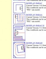
I cannot find any information on what the Hornresp Paraflex model schematics ('Type 1, 2, 3, 4') actually represent.
I know the way you fold the cabinet is not the same thing as the schematic.. But I can't tell what is implied by the circles around the tap or throat points and the extra segments (6,7,8,9), though I have found their cross sectional area is represented in the Schematic 1 window.
Any ideas?
Hi,Hi there,
I cannot find any information on what the Hornresp Paraflex model schematics ('Type 1, 2, 3, 4') actually represent.
I know the way you fold the cabinet is not the same thing as the schematic.. But I can't tell what is implied by the circles around the tap or throat points and the extra segments (6,7,8,9), though I have found their cross sectional area is represented in the Schematic 1 window.
Any ideas?
Have you look at this? it will give you some ideas I think . Good luck !
http://www.diysubwoofers.org/sheets/