Hi All.
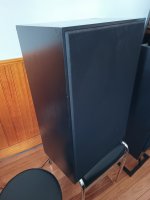
Just came across a pair of 3 Way Loudspeakers which I'd like to freshen up.
Previous owner said the high notes were absent.
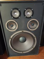
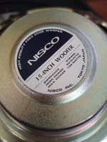
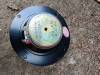
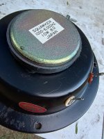
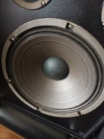
Each enclosure has 1 x15" Nisco Woofer, 2 x 3 1/2" Japanese Mids, 2 x 2 1/2" Japanese Tweeters.
Firstly I found a non soldered section of wire feeding the mid drivers had separated.
The other thing, that puzzles me, is that the mid capacitor is feeding the -ve terminal on the mid range speakers.
Existing crossovers:
+ve signal to large air core inductor, then to +ve terminal on woofer.
+ve signal to 8 µF electrolytic cap, then to -ve terminal on midrange speakers.
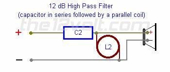
+ve signal to 2.8 µF electrolytic cap, then split, one going to +ve terminal on tweeter speakers, and another going to a smaller inductor which then goes to -ve return.
Is this correct?
Should the 8µF electrolytic cap be feeding the negative on the midrange drivers?
And, is it normal to have the 2.8µF cap feeding both the tweeters & an Inductor (especially as the Inductor then goes back to -ve enclosure terminal)?
Also, are these drivers of any value(the 15 inch drivers look like they could move some air)?
Just came across a pair of 3 Way Loudspeakers which I'd like to freshen up.
Previous owner said the high notes were absent.
Each enclosure has 1 x15" Nisco Woofer, 2 x 3 1/2" Japanese Mids, 2 x 2 1/2" Japanese Tweeters.
Firstly I found a non soldered section of wire feeding the mid drivers had separated.
The other thing, that puzzles me, is that the mid capacitor is feeding the -ve terminal on the mid range speakers.
Existing crossovers:
+ve signal to large air core inductor, then to +ve terminal on woofer.
+ve signal to 8 µF electrolytic cap, then to -ve terminal on midrange speakers.
+ve signal to 2.8 µF electrolytic cap, then split, one going to +ve terminal on tweeter speakers, and another going to a smaller inductor which then goes to -ve return.
Is this correct?
Should the 8µF electrolytic cap be feeding the negative on the midrange drivers?
And, is it normal to have the 2.8µF cap feeding both the tweeters & an Inductor (especially as the Inductor then goes back to -ve enclosure terminal)?
Also, are these drivers of any value(the 15 inch drivers look like they could move some air)?
Attachments
Last edited:

The basic crossover layout seems OK - inductor in series with woofer, capacitor in series with mids and 2nd order LC fllter (see attachment) on tweeters.
Midrange drivers are often connected in reverse polarity.
You can experiment with the midrange polarity i.e. connect the 8 uF to the +ve midrange terminal. Choose the polarity that sounds best to you.
I'm not familiar with the brand, but the drivers (particularly the mids and tweeters) look to be of no great monetary value.
Attachments
Thanks G.
Excellent reply.
I don't want to over capitalize so I'm thinking of just replacing the electrolytic caps with new examples.
I'll follow your instruction of swapping the mid polarity to listen for improvements.
The boxes are sealed (no port).
Although not top of the line, I think these should put out satisfying bass from the 15" woofers.
Not sure, but I see a lot of potential in them.but the drivers (particularly the mids and tweeters) look to be of no great monetary value.
So far, I've soldered the twisted wires some of which had separated and resulted in loss of signal to some of the drivers.
Also I I soldered a pair of 2.7uF Dayton poly caps in place of the 2.8uF LCC electrolytics These were left over from a previous makeover.
The redundant 2.8uF electrolytic caps were branded LCC and tested at 3.9uF.
Also I I soldered a pair of 2.7uF Dayton poly caps in place of the 2.8uF LCC electrolytics These were left over from a previous makeover.
The redundant 2.8uF electrolytic caps were branded LCC and tested at 3.9uF.
I've found high ESR electrolytic caps are usually also high in value. Could be a reason the "highs are missing". High ESR (equivalent series resistance) is the worse effect.The redundant 2.8uF electrolytic caps were branded LCC and tested at 3.9uF.
It makes sense.I've found high ESR electrolytic caps are usually also high in value. Could be a reason the "highs are missing". High ESR (equivalent series resistance) is the worse effect.
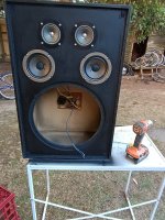
On one enclosure the wiring to the midrange drivers was disconnected.
Add high ESR and the end result appears to be low treble.
I finally pulled put some time into finishing these.
Resprayed the boxes (matt on front baffles, low sheen for the rest of the boxes).
As these are "no name" speakers I wanted to keep costs to a minimum.
I was very happy with the existing Inductors as they were air core from the start.
The 8µF mid driver electrolytic caps were replaced with a collection poly caps of various values fitted in parallel to each other.
After spending $15 in total I was pleased with the result.
They take high volume without breaking up.
The highs and mids are strong.
Reasonable bass.
Closing my eyes there is a sound stage.
Need more time with them but happy with the result.
Thanks for everyones input.
Attachments
-
 15 inch speakers 3.jpg401 KB · Views: 99
 -
 15 inch speakers 4.jpg322.1 KB · Views: 91
 -
 15 inch speakers 5.jpg452.7 KB · Views: 119
 -
 15 inch speakers 6.jpg579.4 KB · Views: 86
 -
 15 inch speakers 7.jpg411.1 KB · Views: 89
 -
 15 inch speakers 8.jpg411.1 KB · Views: 90
 -
 15 inch speakers 9.jpg293.9 KB · Views: 93
 -
 15 inch speakers 10.jpg454.2 KB · Views: 103
If you are happy with the crossover I would look at the cabinets . They would probably benefit from some wall to wall bracing - and some internal wall dampening - I have used carpet tiles with good results as the tiles often have a bitumen type layer. Some light internal filling might also have benefit.
The layout of the drivers is 'unusual' I wonder if the horizontal dispersion would be better with the speakers laid on their sides. I guess it would depend on their height dependent to the listener as I suspect they must produce a complicated dispersion pattern.
The layout of the drivers is 'unusual' I wonder if the horizontal dispersion would be better with the speakers laid on their sides. I guess it would depend on their height dependent to the listener as I suspect they must produce a complicated dispersion pattern.
Thanks X.If you are happy with the crossover I would look at the cabinets . They would probably benefit from some wall to wall bracing - and some internal wall dampening - I have used carpet tiles with good results as the tiles often have a bitumen type layer. Some light internal filling might also have benefit.
The layout of the drivers is 'unusual' I wonder if the horizontal dispersion would be better with the speakers laid on their sides. I guess it would depend on their height dependent to the listener as I suspect they must produce a complicated dispersion pattern.
Coincidentally, I often mount loudspeakers on their sides depending on the furniture and whether I'm standing or not.
Also looks cool.
Damping is a good idea but can be taken too far on some projects.
A pair of loudspeakers I treated last year resulted in a dead/lifeless sound.
- Home
- Loudspeakers
- Multi-Way
- Assistance to refreshen up crossovers on a Non Branded Pair of Loudspeakers