It has been in my stars to make an 859, even though I was not totally smitten with it the first time.... Fast forward almost 30 years and several 3-6 watt SE builds later, I figured an 859 at 12 watts seemed like an idea. But really heading towards 20 watts would be more satisfying, and the nearest TX I have is a nominally 20 watt chinese, at 3.5K, rather than dp's 4.6k, so I came up with the idea of running the 509 in parallel with a PL504, which seems superficially like half a 509 spec wise. This build has been rumbling in the back ground for a while, whilst still building up courage and accumulating parts for my 13E1 and GM70 SE amps. A little iron related pause on my PP triode amp, has spurred me back on tho the 859. It is more of an 869, with improved bias stability loop by the LTP input stage,
http://www.troelsgravesen.dk/EAR-869.htm
thanks Troels for posting the circuit. I have had to mod it a little because I can't help myself and to cope with the extra tube into the DC loop. This is additionally complicated by another bright idea, Eco mode. I live quite happily with 3 watt SEs 95 percent of the time, and I know myself I will not be putting on a hefty tube guzzler for background listening, so I have arranged to be able to switch out the 509 by turning the heater off.

Well it is almost working, after a bit of head scratching over the DC loop being very saturated I realised yesterday I had some 22ks instead of 2k2s in the output tube's G1 potential divider, and had the cathode follower divider upside down as well. That fixed, it burst in to life. Now I optimistically figured I would be able to get away with 450V HT, but that isn't going to work, and I have exploded one 450V cap so far. with both tubes running it gives around 11 watts. I need to jack up the HT to around 530, similar to dp's value to get the desired output. This is going to need some higher voltage re-capage, nuisance.

Heater test, A problem in itself with 6.3v 40v 27v and 42 volt tubes.

To be continued.
http://www.troelsgravesen.dk/EAR-869.htm
thanks Troels for posting the circuit. I have had to mod it a little because I can't help myself and to cope with the extra tube into the DC loop. This is additionally complicated by another bright idea, Eco mode. I live quite happily with 3 watt SEs 95 percent of the time, and I know myself I will not be putting on a hefty tube guzzler for background listening, so I have arranged to be able to switch out the 509 by turning the heater off.
Well it is almost working, after a bit of head scratching over the DC loop being very saturated I realised yesterday I had some 22ks instead of 2k2s in the output tube's G1 potential divider, and had the cathode follower divider upside down as well. That fixed, it burst in to life. Now I optimistically figured I would be able to get away with 450V HT, but that isn't going to work, and I have exploded one 450V cap so far. with both tubes running it gives around 11 watts. I need to jack up the HT to around 530, similar to dp's value to get the desired output. This is going to need some higher voltage re-capage, nuisance.
Heater test, A problem in itself with 6.3v 40v 27v and 42 volt tubes.
To be continued.

Here is today's circuit:

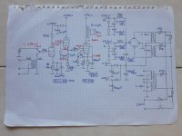
This is the HT supply. 240mA represents Left and right outputs

This is the heater supply. Consisting of a 24-0-24 >100VA transformer and a 30VA 6-0-6. There is a bit going on, with the 6-0-6 being used to supplement the 48v. 48v + 6 to give 54 volts for two PL504s in series, and 48-6 giving 42 volts for PY500 and 40 volts with a dropper for the PL509s. The small valves are DC in series, and raised 30v above ground. The ECC85 takes more current than the ECc88, so a bypass resistor to help there.

This is the HT supply. 240mA represents Left and right outputs
This is the heater supply. Consisting of a 24-0-24 >100VA transformer and a 30VA 6-0-6. There is a bit going on, with the 6-0-6 being used to supplement the 48v. 48v + 6 to give 54 volts for two PL504s in series, and 48-6 giving 42 volts for PY500 and 40 volts with a dropper for the PL509s. The small valves are DC in series, and raised 30v above ground. The ECC85 takes more current than the ECc88, so a bypass resistor to help there.
Attachments
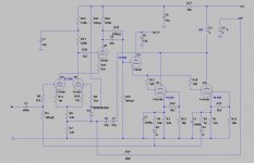
In the amp circuit diagram above, the node labeled "this_node" has given me some cause for thought. The grids of the ECC88 are around 20 volts, "this_node" is about 22 volts. I think this is right, as it works, but surprisingly low voltage.
Not full of joy at the moment. Have increased the HT to 520v. Nothing has exploded and seems quite happy with new higher voltage capacitors, which is good, but the power output is still around 12watts. I think now the driver is not powerful enough and / or not enough swing. I don't fully understand what is going on, and currently trying to remember how to put models in to LT spice so I can simulate it, to try and get a better fix. Very tempting to put a MOSFET between the cathode follower and the screen grids. Maybe just for the 509, it is not the limitation on the 504.
I think half an ECC85/6AQ8 simply doesn't prvide enough power to drive the screens, not even for a single PL504's. As in the Danielak design, you'd need a small power pentode here.
Another question: What do diodes D2 and D3 do in your amp circuitry? If you want to feed the sum, or the average, of both cathode voltages back to the 1st triode, you'd need to go another way. The diodes will feed back just one voltage or the other (the higher one of both).
Best regards!
Another question: What do diodes D2 and D3 do in your amp circuitry? If you want to feed the sum, or the average, of both cathode voltages back to the 1st triode, you'd need to go another way. The diodes will feed back just one voltage or the other (the higher one of both).
Best regards!
The ECC85 is dp's choice, the current "at rest" from the cathode follower is only 2-3 mA, but definitely getting a flat top when trying to drive the 509 and 504 together at full output. This is the second time I have got in trouble doing a non identical "copy" of a dp circuit. I think Mosfet is the way to go for a quick and dirty test. Alternatively the power pentode is a good idea, an CL8 type would fit. I would need to find one with a C which is similar to the ECC85 for the top of the cascode I guess.
The diodes are part of the DC stability loop. As I want to run it with or without the 509, the diodes allow whichever tube is pulling the most current to control the loop. I haven't proved it is a bad idea yet. It definitely works, but may need some cathode resistor value tweaking to get a fair balance with both tube running.
The diodes are part of the DC stability loop. As I want to run it with or without the 509, the diodes allow whichever tube is pulling the most current to control the loop. I haven't proved it is a bad idea yet. It definitely works, but may need some cathode resistor value tweaking to get a fair balance with both tube running.
Last edited:
Well, I'm impressed at attempting such an unusual output tube combo. Aside from the ECC85 possibly not handling the drive currents, I think the 2nd bug here is the differing mu factors of PL504 (mu 6 to 7 ) and PL509 (mu 3.2 to 3.3 ). As the grid 2 drive increases, the PL504 will not be keeping up. Dropping out as a fraction of the total current output.
The differing effective tube drives might be use-able for a linearizing effect though. Helping to counter the increasing tube gm with current. Interesting idea. This would definitely need some simulating to find the optimum mu mis-match and initial biasing.
The differing effective tube drives might be use-able for a linearizing effect though. Helping to counter the increasing tube gm with current. Interesting idea. This would definitely need some simulating to find the optimum mu mis-match and initial biasing.
Last edited:
With both of these demands, a PCL200 should be in the ballpark: Triode almost the same as half a 12AT7, high gm frame grid video power pentode of the last technology in tube development.Alternatively the power pentode is a good idea, an CL8 type would fit. I would need to find one with a C which is similar to the ECC85 for the top of the cascode I guess.
Best regards!
Lots to think about. mu, that's voltage gain right? when driven by the screen grid. hmmm. I guess with G2 drive, the output is no longer as good a current source? That is implied by some of the feedbackless designs around. I have identified the ECL85 as another possible contender. I have some close relatives in my stash, I am sure. I will have a go with the mosfet this weekend and see how that works and wire up the other channel with the ECL85 type if it looks promising.
Yippee 21 watts, with a mosfet buffer for the g2 driving the 509. Everything is running a bit rich though, and the DC loop is misbehaving again 40 watts and 20 watts for the 509 and 504. Simulation time.
It lives and makes music....

Has gone together fairly well, and I am much happier testing it upside down, as above, rather than up on end like a tombstone, which is quite nice for building, but a bit scary for testing, as it feels too near to my face. Had two caps blow up early on..... Apart from that, the other interesting problem, quite a lot of hum. Realised the whole heater circuit was floating, or so I thought. Grounded the heater circuit, only to find a buzz coming from one output, with only the heaters on, and no HT. Puzzled over that for a while but eventually found heater supply had a short to one of the PL504s G2. It is suddenly much happier with that removed!
The other problem is going to require some creative arm twisting. I was getting about 2 watts from the PL504s by themselves using the 8 ohm tap, so I tried the 4 ohm tap, and got 4.5 watts. Thats nice, so I have incorporated a relay to switch taps when in "eco" mode. The amp actually runs really nicely in eco mode. The HT rises to about 550 volts with the light load of about 80 mA. Switching in both 509s however pulls the HT down to 430 volts (270mA). Testing with one 509 was not too bad for sag, and I got 21 watts output, but 430v with both 509s running is not that good, and it really is not happy. I should be getting 10 watts, but subjectively no increase in level.
Initial attempts to help with the power supply sag, I have incorporated a permanently powered PY83 (110 ohms) in parallel with the PY500 (45 ohms) that is now is switched in with the 509s. There are several problems. The large inductor which came with the box, its series resistance is 140 ohms, so that is losing almost 40 volts. Looking at the high power mode output waveform, it is clipping at the bottom, so I am going to back off the current. That will help the head room a bit as well. Lots of things to try. The HT transformer runs quite hot, but it is "new" and should be good for 100 watts.
Last edited:

- Home
- Amplifiers
- Tubes / Valves
- EAR 859/869 inspired amp build.