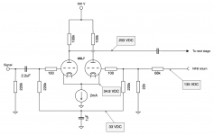
I'm currently fiddling around with a tube preamp prototype, in which I've decided to try out using a 6SL7 differential amplifier/LTP as a front end. The operating point is set using a cascoded BJT-CCS in the tail. This is then AC-coupled to a grounded-cathode amplifier stage, which is DC-coupled to a cathode follower as a final stage. Both of these stages uses a single 6SN7.
To make it easier to stabilize the NFB-loop, I have tried to DC-couple the feedback path from the cathode follower to G2 on the input stage LTP. Therefore, the grids are elevated to 33 V by the voltage divider in the NFB-network, and a capacitor provides the AC-ground path for each grid-leak resistor.
I've noted that the elevated grid circuit is having issues with low frequency oscillation at <1 Hz. This is without signal, an is probably started by grid current from the first half of the 6SL7 (?). I discovered it when measuring the DC-voltage (33 V in the schematic), and found that it is fluctuating up and down slowly. Am I missing something obvious here? Is there some simple way to stabilize this elevated grid circuit? Increasing the capacitance will only slow down the time constant, and then it takes ages for the cap to charge up.
Attachments
Last edited:
Try increasing the 1uF significantly, or else decrease the output coupling capacitor.
There is excessive loop LF phase shift, causing instability.
There is excessive loop LF phase shift, causing instability.
Last edited:
You have NFB to the right triode and PFB to the left one via the two 220k resistors.
To stop the oscillation make the loop gain for very low frequenties less with smaller coupling capacitors to the finals.
Mona
To stop the oscillation make the loop gain for very low frequenties less with smaller coupling capacitors to the finals.
Mona
If the CCS is passing 2 mA the voltage drop over the plate resistors would have to be 100 V. The plate voltage would then be 250 - 100 = 150 V. But the schematic indicates 203 V as the plate voltage of the left side triode.
rayma: I had 330 uF previously, but then it took ages to charge the cap. I'll try something in between and wait it out to see the results. You and Ketje are referring to the same coupling capacitor, right? The one from the left 6SL7 anode feeding the next stage?
Ketje: Oh! That's something I had missed out on. Off course you are right, the cap won't shunt infinitely low frequencies to ground, and some will be passed to the left grid through it's grid-leak resistors. Then the reasoning with the coupling capacitor also makes sense to me. Now, the coupling cap value is 0,22 uF, and the next stage is grounded with 470k, so Fc is around 1,5 Hz.
PFL200: Thanks for pointing that out, I forgot that I've increased the B+ voltage to 300 V. Each resistor drops about 100 V. I have updated the schematic in my first post.
Increase the value of the 1uF from the input grid resistor to ground by at least x5, or more if needed.
If that is not possible, significantly decrease the value of the coupling capacitor from the plate,
by at least 1/5 times.
If that is not possible, significantly decrease the value of the coupling capacitor from the plate,
by at least 1/5 times.
Great, I'll try it out! I hope that will do, not sure if I have any high voltage capacitors at around 47 nF at hand.
For testing purposes, even 10nF or 20nF will do. Those values should certainly work.
Or connect two 0.1uF in series, for 0.05uF.
Or connect two 0.1uF in series, for 0.05uF.
Probably you could get rid of the 1uF capacitor, and increase the 2 x 220k resistors to, say 1M. Then the grids will be at the same DC potential, but negligible positive feedback will go to the input.
Question:
You are getting negative feedback, all the way from what?
Please post a schematic of the next stage where the negative feedback is coming from.
Single Circuits by themselves might work in isolation.
But two Circuits that are connected together, might need to be analyzed together, in order to make them work.
A blindfolded archer has trouble hitting the bulls eye.
Just my opinions.
Icsazar: Ah, and just ground each resistor? Maybe I'm missing something obvious here, but wouldn't that offset the first (0 V) and second grid (33 V)?
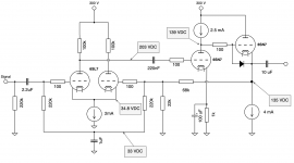
6A3sUmmer: Yes, fair point. Here is the full schematic of the circuit in it's current state. The negative feedback is DC-coupled from the cathode follower. No components for HF-compensation is drawn in yet.
6A3sUmmer: Yes, fair point. Here is the full schematic of the circuit in it's current state. The negative feedback is DC-coupled from the cathode follower. No components for HF-compensation is drawn in yet.
Attachments
Last edited:
No ground, just connect a 1M resistor beween the grids. So the grids will be at the same DC potential. AC operating conditions will be different: input signal will act mostly on the left tube, feedback signal will act mostly on the right tube.lcsaszar: Ah, and just ground each resistor? Maybe I'm missing something obvious here, but wouldn't that offset the first (0 V) and second grid (33 V)?

now the grid of the left 6sn7 has no DC reference, grid connects with coupling cap and ... nothing else; drawing error or reality ...?... Here is the full schematic of the circuit in it's current state. ...
Check the circuit again. The biasing would not work properly with a resistor to ground.
The input grid is biased from the cathode follower output, through the two 220k resistors, and the 22k to ground.
This sort of diff amp biasing has been commonly used, such as in Luxman, McIntosh, and Marantz amplifiers.
The input grid is biased from the cathode follower output, through the two 220k resistors, and the 22k to ground.
This sort of diff amp biasing has been commonly used, such as in Luxman, McIntosh, and Marantz amplifiers.
Attachments
Last edited:
You really, really don't want to bias the signal input / left-most 6SL7 from the feedback, as Ketje has already explained. Instead, it needs its own bias supply of +33VDC not derived from the feedback. A bypassed voltage divider from B+ would be fine.
All good fortune,
Chris
All good fortune,
Chris
Try replacing the 220nF coupling capacitor with a 47nF followed by a grid leak of 470k.
Like that the loop gain for very low frequencies is less.
Mona
Like that the loop gain for very low frequencies is less.
Mona
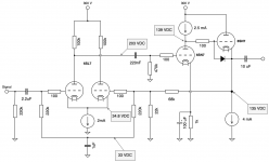
🤦♂️Drawing error. It is off course referenced to ground through a grid leak (470k). See the attached image.now the grid of the left 6sn7 has no DC reference, grid connects with coupling cap and ... nothing else; drawing error or reality ...?
lcsaszar, rayma: Thank you for the explanations. Yes, now it's starting to make sense.
Chris Hornbeck: OK! I will try that too. If I understand your suggestion correctly, it will off obviously isolate the first/leftmost grid from any (positive) feedback signal, really low frequencies included. I'm still a bit curious if I can get the current circuit stable with increased decoupling capacitance though. I will do some practical tests, to be continued...
Thank you all for your advice so far. This really helps my understanding of tube circuits, a subject that is still quite new to me. I've been away from home during the weekend, but will be back home soon, to fire up the soldering iron! 😎
Attachments
still the voltages are not logical . you have 139V on the anode of the first SN tube and 135V on the cathode of the follower. that cathode operates with 4V positive grid voltage ?
That 1uF deooupling cap is too small as was observed ... I would use at least 10uF and a good quality one with low ESR
- Home
- Amplifiers
- Tubes / Valves
- Stability issues in LTP with elevated grid