Not as familiar with MTX amps as the others.
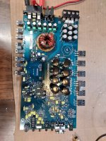
This amp uses 75339P PS FETS. I've never seen them before.
Is it normal for these power supply mosfets to heat up so quickly?
I know it is not in the heatsink, but I have never had power supply mosfets get this hot in only a few seconds. From my experience the outputs are the ones you must pay special attention to.
The gate resistors are 61R9 and read good.
R117 in the pic reads good but is very discolored. Would it be wise to replace it with a higher wattage?
Attachments
The 75339s are common in the MTX amps.
I've seen one model that had a problem with the FETs heating up. I tried virtually everything short of replacing the transformer and they still got hot. It happened on all of that model (a 5 channel amp). When the FETs were clamped the heatsink heated up slightly but not anything near what I'd consider warm. I can't say for certain that the heating is normal for this amp.
Make sure that the 10 ohm resistors between the base and emitter of the driver transistors are within tolerance.
If the resistor is part of a snubber and the cap is within tolerance, you could go to a higher wattage.
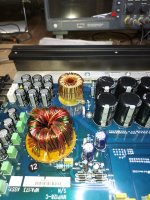
It's been a while, but finally got back on this one. The original problem was that it had a shorted output inductor. I could hear it, but I couldn't see it even with the lights off. I removed the inductor and started unwinding and checking it.
I suddenly got and idea. I got a bowl of hot water, placed my ohmmeter probes in it and started adding salt until I could see the ohms drop. The saline solution is conductive. I then connected one probe to the end of the coil winding, kept the other probe in the saline and slowly feed the wire from the inductor through the solution until I read a low ohm reading. It worked like charm.
I ended up almost totally unwinding the inductor. There were many shorts. I used shrink wrap to insulate all of the shorted areas and tested them in the saline. I then started winding the inductor. There was so much shrink wrap that it was very difficult to wind and the shrink wrap would move when I pulled on the wire to get it tight. (Attached is a photo of the device I made based on Perry's design and screwed to a door facing to get the windings tight.)
When I tried to re-install the inductor, there was hardly any room for the little thermistor to fit in the center and the amplifier was still just not working properly.
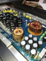
I then totally unwound the inductor and ordered some wire. I rewound the inductor. It isn't perfect but I was pleasantly surprised that every thing is now working as it should on my workbench. I attached photos of the rewound inductor. I know it is not perfect but I have learned a lot.
I had also found that the sil-pad type material used as the insulators for the mosfets was crumbly. It was very difficult to get the residue off of the heatsink. Scotch-Brite and elbow grease work really well. I used mica insulators and applied new compound.
I suddenly got and idea. I got a bowl of hot water, placed my ohmmeter probes in it and started adding salt until I could see the ohms drop. The saline solution is conductive. I then connected one probe to the end of the coil winding, kept the other probe in the saline and slowly feed the wire from the inductor through the solution until I read a low ohm reading. It worked like charm.
I ended up almost totally unwinding the inductor. There were many shorts. I used shrink wrap to insulate all of the shorted areas and tested them in the saline. I then started winding the inductor. There was so much shrink wrap that it was very difficult to wind and the shrink wrap would move when I pulled on the wire to get it tight. (Attached is a photo of the device I made based on Perry's design and screwed to a door facing to get the windings tight.)
When I tried to re-install the inductor, there was hardly any room for the little thermistor to fit in the center and the amplifier was still just not working properly.
I then totally unwound the inductor and ordered some wire. I rewound the inductor. It isn't perfect but I was pleasantly surprised that every thing is now working as it should on my workbench. I attached photos of the rewound inductor. I know it is not perfect but I have learned a lot.
I had also found that the sil-pad type material used as the insulators for the mosfets was crumbly. It was very difficult to get the residue off of the heatsink. Scotch-Brite and elbow grease work really well. I used mica insulators and applied new compound.
Attachments
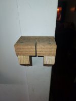
Using a block like that really helps to get the windings tighter and reduces hand fatigue (for me, anyway).
For those using mica insulators, it's important that they are purchased from reputable manufacturers so that they are consistent in thickness. Many times, budget mica insulators are varying thicknesses and that can cause problems because they won't conduct heat equally.
The addition of, even a short length of heatshrink tubing or fiberglass sleeving, can make the windings too short.
Did you do anything to prevent the inductor from moving/vibrating?
Yes. Goop works really well.Using a block like that really helps to get the windings tighter and reduces hand fatigue (for me, anyway).
For those using mica insulators, it's important that they are purchased from reputable manufacturers so that they are consistent in thickness. Many times, budget mica insulators are varying thicknesses and that can cause problems because they won't conduct heat equally.
The addition of, even a short length of heatshrink tubing or fiberglass sleeving, can make the windings too short.
Did you do anything to prevent the inductor from moving/vibrating?