Helo i wanted to control amplifier bias.
But I don't know how.to connect it. Any one can tell about it. It may also help others who are beginner in to the electronics...
Thanks In advance..
But I don't know how.to connect it. Any one can tell about it. It may also help others who are beginner in to the electronics...
Thanks In advance..
Attachments
Last edited:
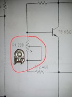
Usually, the "TOP" as in your picture is the wiper.
You can verify that by looking closely or by testing with an ohm meter.
You can verify that by looking closely or by testing with an ohm meter.

Thanks For Reply But How And Where To Connects It's 1st 2nd Or 3rd pin Can U Configure Pin Outs In picture?Usually, the "TOP" as in your picture is the wiper.
You can verify that by looking closely or by testing with an ohm meter
Tvrgeek???Usually, the "TOP" as in your picture is the wiper.
You can verify that by looking closely or by testing with an ohm meter.
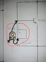
Use the middle pin of the preset and either one of the end pins. Leave the other pin unconnected. Maximum resistance (so set at 200 ohm) will give minimum bias current.
Depending which end pin you use determines whether bias goes up or down with clockwise rotation so its your choice as to what seems best and whether access to the preset is from above or below.
Depending which end pin you use determines whether bias goes up or down with clockwise rotation so its your choice as to what seems best and whether access to the preset is from above or below.
Thanks Mooly The Best Guider On DiyAudio.com ever...Use the middle pin of the preset and either one of the end pins. Leave the other pin unconnected. Maximum resistance (so set at 200 ohm) will give minimum bias current.
Depending which end pin you use determines whether bias goes up or down with clockwise rotation so its your choice as to what seems best and whether access to the preset is from above or below.

Or what is difference between diodes bias control or variable bias control or resistors bias control???
Yes, and as you look at that picture the bias current will increase as you turn the pot clockwise.Is It Ok Now???
Diodes can be used for temperature compensation but they have to be in thermal contact with the heatsink. As the heatsink gets hotter, the voltage across the diodes falls a little and that pulls the bias back down.Or what is difference between diodes bias control or variable bias control or resistors bias control???
Your circuit with the transistor is called a vbe multiplier and the transistor should be in thermal contact with the heatsink.
https://en.wikipedia.org/wiki/Rubber_diode
ThanksYes, and as you look at that picture the bias current will increase as you turn the pot clockwise.
Diodes can be used for temperature compensation but they have to be in thermal contact with the heatsink. As the heatsink gets hotter, the voltage across the diodes falls a little and that pulls the bias back down.
Your circuit with the transistor is called a vbe multiplier and the transistor should be in thermal contact with the heatsink.
https://en.wikipedia.org/wiki/Rubber_diode
👍- Home
- Amplifiers
- Solid State
- Want To know About Variable Connections..