Depends on the circuitry, but probably not much of the time.
But you can often infer that there is some leakage, by measuring DC voltage on the following resistor to ground
(with the power on), unless the following part of the circuit is at a non-zero DC potential.
But you can often infer that there is some leakage, by measuring DC voltage on the following resistor to ground
(with the power on), unless the following part of the circuit is at a non-zero DC potential.
What Rayma said. Pull out the following tube and measure the DC voltage across the following resistor to ground as long as it’s auto bias and not fixed bias. Should have no DC on it. How old and what kind of caps?
Is this for a tube preamp, or tube power amp? A leaky coupling capacitor in a tube power amplifier
can play havoc with the output tube bias, especially those old Black Cat capacitors, like in the Dyna amps.
Sometimes you can't pull a tube because the tube filaments are connected in series.
can play havoc with the output tube bias, especially those old Black Cat capacitors, like in the Dyna amps.
Sometimes you can't pull a tube because the tube filaments are connected in series.
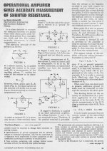
Look at the schematic and see what the current paths around the coupling cap in question are when tubes are nonconducting. In the Princeton Reverb, there are 0.1uF caps ahead of each power tube. For one of them, each side has a resistance path to ground and for the other, one side has a resistance path to ground and the other has a resistance path to the V1 power supply, so you're also depending on the absence of leakage in the power supply filter caps. Therefore you'd have to lift a leg of either of those to test them at all.
Hi , Everyone. I should have been more specific. It is a power amplifier ( 2 mono blocks ) VTL MB 250 with 8 6550 WE tubes in each. I see the coupling caps .47uf each ( there what seem to eight of them ) and they seem to be polypropylene types. Bias is not auto bias as there are trim pots for manual bias. So far I am not seeing any tubes appearing to have red plates . I have the tubes biased at about 250mv ( across 10 watt resistors) and will hook them up to my friends speaker soon and tweek them to be between 270-300mv . I imagine these amplifiers are more than 20 years old. When I got them one was blowing the main fuse on turn on and I saw a leaky power cap which I renewed in both amplifiers ( four power capacitors in all) . In addition with the same amplifier, the B+ fuse blew when the amplifier volume was increased. At night in the dark there were three tubes that seemed a bit brighter at the base of the tubes and I substituted them with spare tubes that I had. Since then the amplifier plays fine ....so far. The other amplifier had no sound at all and I traced it to a 5Watt 20K resistor that had opened up. It played after I replaced the resistor. The affected tube that was not receiving any plate voltage due to this bad resistor was a 6350 tube. Both of these tubes , one in each amplifier appear to produce the same amount of heat , when measured with an infra red thermometer.
Last edited:
Very doubtful that they are leaking. Polypropylene are not prone to problems. A lot are self healing types.
F
I'd periodically check the values of those, which can be done in-circuit with the power off.
Probably 10 ohms each.
In that amp, it's much more likely that the 10W bias measurement resistors can be damaged.I am happy to hear that
I'd periodically check the values of those, which can be done in-circuit with the power off.
Probably 10 ohms each.
Thank you rayma. Yes ! I checked those 10 W resistors and they all seem fine and within tolerance at the moment. It is good to know that these should be checked now and again.
Regards
Paul
Regards
Paul

- Home
- Amplifiers
- Tubes / Valves
- How to test coupling capacitors in situ?