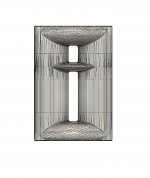
I wanted to try the open baffle thing and have purchased a few speakers to play with, Goldwood 8024 8" (high QTS), GRS Neo3 clones (only ~$30!), and some older Madisound Neo8 clones. I'm also pretty handy with CAD and 3D printing, so I purchased the CAD files for the Neo3 horn that Joseph Crowe offers.
https://josephcrowe.com/products/es-1600-biradial-horn-for-bg-neo3-3d-cad-files
I modified his design to also hold a Neo8; even though the body of the Neo8 is wider, it has the exact same width 4-hole wide arrangement across. I think it would be amazing to 3D print the horn with a Bronze-filled filament and polish them up a bit.
https://colorfabb.com/5-years-bronzefill
I'm a little bit concerned with running a first-order cross-over between the Neo3 and Neo8, and would appreciate yalls thoughts.
https://hometheaterreview.com/first-order-crossovers-panacea-or-problem/
As mentioned in the above article,
"The other problem with first-order crossovers is dispersion. Because the filters are relatively shallow, both drivers are simultaneously audible when sounds are within about an octave of the crossover frequency. This is no problem if your ears are at the same distance from the drivers. However, if your ears are closer to one driver–if you stand up, which puts your ears closer to the tweeter, or slouch down, putting your ears closer to the woofer–the sounds from the two drivers will no longer be in phase at all frequencies. They’ll be in phase at some frequencies and out of phase at others, which means some frequencies will be boosted and others attenuated, and you will no longer be getting even frequency response. (Speakers with higher-order crossovers can also have this problem, but to a much lesser degree.)"
How likely is dispersion to be an issue? What's the best way to measure dispersion effects?
Attachments


With dipoles, you must forget those Xsim sims.
Take measurements at roughly 1m (3'), also off-axis at 10deg intervals up to 90 deg (or more likely up to 180) Use ARTA or REW (RoomEqWizard)
Study real acoustic response and distortion (spl 90dB at 1m)
Based on measured data, start to figure out crossover points and slopes, and timing etc. You will soon notice some serious challenges...
VituixCAD is a very good freeware simulation, but also very challenging to learn...
Thank you for the response and resource! I look forward to playing with VituixCAD tonight. I used REW, a UMIK1 and my DATS to take the measurements (on-axis @1m) that I used in that XSim simulation posted above. The measurements were un-gated though, so I'll likely redo the measurements gated tonight.With dipoles, you must forget those Xsim sims.
Take measurements at roughly 1m (3'), also off-axis at 10deg intervals up to 90 deg (or more likely up to 180) Use ARTA or REW (RoomEqWizard)
Study real acoustic response and distortion (spl 90dB at 1m)
Based on measured data, start to figure out crossover points and slopes, and timing etc. You will soon notice some serious challenges...
VituixCAD is a very good freeware simulation, but also very challenging to learn...
I had another crazy idea. What if I horn loaded the planar magnetics from both sides?! Would I get further low-end extension?
Yes...but not much: https://community.klipsch.com/index...eritage/page/16/&tab=comments#comment-2452137What if I horn loaded the planar magnetics from both sides?! Would I get further low-end extension?
Chris
Thank you for the link! Very interesting, in that case the double loading would enable a 600 hz vs a 1000hz cross over! Definitely seems worth experimentng with.
Hello guys! That Klipsh forum link is comparing 7" vs 12" wide wings, and only looking at frontal response.
That is totally irrelevant considering a dipole multiway project!
Gigapunk, please study the basic physics and challenges of dipole radiation from loudspeaker drivers. some of best resource is linked below. The basic idea and challenge is that dipole inteference of front and rearside wavefronts is determined by baffle dimensions and frequency. When we want to achieve wide range of dipole radiation pattern, a single driver works only for max 3 octaves before distortion in low end and problematic interferences in upper band became limiting factors.
www.dipolplus
http://musicanddesign.speakerdesign.net/tech.htmlhttps://www.linkwitzlab.com/models.htmhttps://www.hifizine.com/2011/03/refining-a-4-way-open-baffle-speaker-minidsp-2x4/
Try dong actual measurements instead of making statements unsupported by fact...and you will find that the directivity gain is consistent over 90 degrees horizontally (the vertical is controlled by the dipole height), both in the fore and aft directions below 2 kHz down to 600 Hz,. Harmonic distortion (indicative of modulation distortion levels), and phase/group delay also show significant improvement in these lower octaves. That's almost 5 octaves with the horn extension.When we want to achieve wide range of dipole radiation pattern, a single driver works only for max 3 octaves before distortion in low end and problematic interferences in upper band became limiting factors.
Here is an example of a 7-octave horn-loading of a titanium diaphragm compression driver: https://community.klipsch.com/index...on-driver-on-k-402-horn-and-jubilee-bass-bin/ They sound really good.
If this were not true, then the Klipschorn Jubilee would not exist...
Not really......and only looking at frontal response...
See those polar lobes below 2 kHz? That is what the horn extension (wings) controls--and it works extremely well out to 90 degrees included angle of the original driver design coverage, and down to 550-600 Hz.
As noted above, the addition of a rear horn/wing brings an additional 2-3 dB of controlled directivity below 1 kHz. More importantly, it extends the operating band by an additional 2 octaves, downward (2.4 kHz-->600 Hz).
I recommend reading on Beranek's Acoustics (1954), or Olson's Acoustical Engineering (1957) texts, as well as the significantly updated and expanded text by Kolbrek (Dunker & Kolbrek Horn Loudspeaker Systems, 2019) to understand what is occurring.
Chris
^I've done hundreds of actual measurements of dipole radiators, mostly B&G Neo3 and Neo8. Also monopoles with or without horn or waveguide, since 2013.
https://www.diyaudio.com/community/threads/aino-gradient-a-collaborative-speaker-project.231353/

Yes I know what horn loading makes. But here we are talking about dipole/open baffle radiators. Using a horn with a dipole radiator has been tested by others, eg. examples here with double tweeters
https://www.diyaudio.com/community/threads/dipole-tweeter-waveguide.217285/
http://www.htguide.com/forum/showth...a-Zaph-drivers&p=551424&viewfull=1#post551424http://gainphile.blogspot.com/https://www.audiocircle.com/index.php?topic=100145.0https://patents.google.com/patent/EP2129164A1/en
https://www.diyaudio.com/community/threads/aino-gradient-a-collaborative-speaker-project.231353/
Yes I know what horn loading makes. But here we are talking about dipole/open baffle radiators. Using a horn with a dipole radiator has been tested by others, eg. examples here with double tweeters
https://www.diyaudio.com/community/threads/dipole-tweeter-waveguide.217285/
http://www.htguide.com/forum/showth...a-Zaph-drivers&p=551424&viewfull=1#post551424http://gainphile.blogspot.com/https://www.audiocircle.com/index.php?topic=100145.0https://patents.google.com/patent/EP2129164A1/en
Last edited:
To the OP--I recommend trying what you have proposed and finding your own answers. Don't let anyone dissuade you from "trying it". I would, however, be careful about any information that implies "you can't do that" without first asking the question "what am I trying to achieve here".
If I could add any suggestions--I would suggest looking at horn profiles having straight sides near the horn throat, instead of the curved sidewalls that have been shown in this thread. This concerns the polar coverage vs. frequency of the horn itself, and curved horn walls near the throat are not conducive to equal polar coverage at higher frequencies. This is a source of the "horn sound" that has been discussed elsewhere. It also involves the most important loudspeaker performance variable according to Sean Olive's decision hierarchy for loudspeaker performance: equal polar coverage vs. frequency (also called consistent power response). This has been something that I've found to correlate to better sounding loudspeakers in real listening rooms.
I would also take a look at throat horn lenses that can be 3D printed to spread out the vertical polars of a line or planar source driver.
__________________________________________________________________________________________
To Juhazi: I'm not much for "crusading" currently, but there is something significantly different about our assumptions for what constitutes "good sound" using line source or planar area drivers in-room. I do think that there are quite a few "memes" (untested ideas about what constitutes good or acceptable practice) that seem to have crept into the threads that I've opened from your links, above. I don't believe we are going to see eye-to-eye on this subject anytime soon. I would ask that you refrain from saying things like...
This is argumentative and assumptive of what the OP and I are communicating to each other.
Please have a bit more forbearance to preface your remarks with the appropriate conditions and assumptions that you are making so that I have a finite chance of agreeing with your statements. Otherwise, I don't know about you but I tend to react negatively to such blanket phrases. They look like unprovoked attacks--and we don't need any more of those presently in the world today.
Chris
If I could add any suggestions--I would suggest looking at horn profiles having straight sides near the horn throat, instead of the curved sidewalls that have been shown in this thread. This concerns the polar coverage vs. frequency of the horn itself, and curved horn walls near the throat are not conducive to equal polar coverage at higher frequencies. This is a source of the "horn sound" that has been discussed elsewhere. It also involves the most important loudspeaker performance variable according to Sean Olive's decision hierarchy for loudspeaker performance: equal polar coverage vs. frequency (also called consistent power response). This has been something that I've found to correlate to better sounding loudspeakers in real listening rooms.
I would also take a look at throat horn lenses that can be 3D printed to spread out the vertical polars of a line or planar source driver.
__________________________________________________________________________________________
To Juhazi: I'm not much for "crusading" currently, but there is something significantly different about our assumptions for what constitutes "good sound" using line source or planar area drivers in-room. I do think that there are quite a few "memes" (untested ideas about what constitutes good or acceptable practice) that seem to have crept into the threads that I've opened from your links, above. I don't believe we are going to see eye-to-eye on this subject anytime soon. I would ask that you refrain from saying things like...
That is totally irrelevant considering a dipole multiway project!
This is argumentative and assumptive of what the OP and I are communicating to each other.
Please have a bit more forbearance to preface your remarks with the appropriate conditions and assumptions that you are making so that I have a finite chance of agreeing with your statements. Otherwise, I don't know about you but I tend to react negatively to such blanket phrases. They look like unprovoked attacks--and we don't need any more of those presently in the world today.
Chris
View attachment 1030815
I wanted to try the open baffle thing and have purchased a few speakers to play with, Goldwood 8024 8" (high QTS), GRS Neo3 clones (only ~$30!), and some older Madisound Neo8 clones. I'm also pretty handy with CAD and 3D printing, so I purchased the CAD files for the Neo3 horn that Joseph Crowe offers.
https://josephcrowe.com/products/es-1600-biradial-horn-for-bg-neo3-3d-cad-files
I modified his design to also hold a Neo8; even though the body of the Neo8 is wider, it has the exact same width 4-hole wide arrangement across. I think it would be amazing to 3D print the horn with a Bronze-filled filament and polish them up a bit.
https://colorfabb.com/5-years-bronzefill
I'm a little bit concerned with running a first-order cross-over between the Neo3 and Neo8, and would appreciate yalls thoughts.
https://hometheaterreview.com/first-order-crossovers-panacea-or-problem/
As mentioned in the above article,
"The other problem with first-order crossovers is dispersion. Because the filters are relatively shallow, both drivers are simultaneously audible when sounds are within about an octave of the crossover frequency. This is no problem if your ears are at the same distance from the drivers. However, if your ears are closer to one driver–if you stand up, which puts your ears closer to the tweeter, or slouch down, putting your ears closer to the woofer–the sounds from the two drivers will no longer be in phase at all frequencies. They’ll be in phase at some frequencies and out of phase at others, which means some frequencies will be boosted and others attenuated, and you will no longer be getting even frequency response. (Speakers with higher-order crossovers can also have this problem, but to a much lesser degree.)"
How likely is dispersion to be an issue? What's the best way to measure dispersion effec
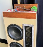
Very cool design. You should compare the rear horn against using a sealed rear chamber. Both serve to lower distortion.
For what it's worth, I noticed in a b and g datasheet for the neo 3 I think it was, they mention that optimal transparency is achieved with the driver open baffle or with an anechoic back chamber ie, a heavily damped back chamber much larger than the back cup provided. There is a similar diy design out there that uses neo8 or neo10 with a coaxially mounted line of planar tweeters in a line array. I'm excited to see what you come up with! BTW, maybe the slot in the ends should be elimated to reduce diffraction. You're so close to an ideal shape you might as well fill that in so pressure wave has no catch at all as it spreads around the corner. Craig
Thank for all of the responses! I just went through Sean Olive's Blogspot, but couldn't find his article on decision hierarchy for loudspeaker performance: equal polar coverage vs. frequency; but I was able to find this one:To the OP--I recommend trying what you have proposed and finding your own answers. Don't let anyone dissuade you from "trying it". I would, however, be careful about any information that implies "you can't do that" without first asking the question "what am I trying to achieve here".
If I could add any suggestions--I would suggest looking at horn profiles having straight sides near the horn throat, instead of the curved sidewalls that have been shown in this thread. This concerns the polar coverage vs. frequency of the horn itself, and curved horn walls near the throat are not conducive to equal polar coverage at higher frequencies. This is a source of the "horn sound" that has been discussed elsewhere. It also involves the most important loudspeaker performance variable according to Sean Olive's decision hierarchy for loudspeaker performance: equal polar coverage vs. frequency (also called consistent power response). This has been something that I've found to correlate to better sounding loudspeakers in real listening rooms.
I would also take a look at throat horn lenses that can be 3D printed to spread out the vertical polars of a line or planar source driver.
__________________________________________________________________________________________
To Juhazi: I'm not much for "crusading" currently, but there is something significantly different about our assumptions for what constitutes "good sound" using line source or planar area drivers in-room. I do think that there are quite a few "memes" (untested ideas about what constitutes good or acceptable practice) that seem to have crept into the threads that I've opened from your links, above. I don't believe we are going to see eye-to-eye on this subject anytime soon. I would ask that you refrain from saying things like...
This is argumentative and assumptive of what the OP and I are communicating to each other.
Please have a bit more forbearance to preface your remarks with the appropriate conditions and assumptions that you are making so that I have a finite chance of agreeing with your statements. Otherwise, I don't know about you but I tend to react negatively to such blanket phrases. They look like unprovoked attacks--and we don't need any more of those presently in the world today.
Chris
https://blogs.qsc.com/systems/2021/11/04/a-deeper-dive-into-loudspeaker-directivity/
I'm very interested in making a vertical polar plot for the neo3 immediately above the neo8 so that I can see if there is any bad behavior with that shallow 1st degree crossover. I'll post up results after I make a baffle.
Great Idea. I already have some neo8s mounted with a 2" rear chamber (half full of natural wool felt). I built these to test out some ideas I had for something similar to a GR Research LS6/9 for my home theatre. I'll try and remember to post up a distortion comparison of these rear chambers vs. a rear horn load. I'll start a new thread on the home theater speakers when I get closer to CNC the baffles, but this project I want to keep open baffle.Very cool design. You should compare the rear horn against using a sealed rear chamber. Both serve to lower distortion.
Attachments
Here is the patent citation (USPTO) for the method used to determine the decision model for loudspeaker performance preferences: https://patents.google.com/patent/US8311232I just went through Sean Olive's Blogspot, but couldn't find his article on decision hierarchy for loudspeaker performance: equal polar coverage vs. frequency...
Here is a pie chart showing the relative weights of the top-level factors as Olive determined from his (above patented) process:
Here is Olive's JAES article on using the method to get his results: https://pearl-hifi.com/06_Lit_Archi...blications/Trained_vs_Untrained_Listeners.pdf
The bottom line from his data is that he says that it's actually "smoothness of sound power" (i.e., consistency/smoothness of polar coverage response) that is most important, with smoothness of on-axis SPL response being the second most important single factor.
Chris
Thanks for the link to the german dipolplus site, I never saw that before! He makes it very clear as to why polars are important:Hello guys! That Klipsh forum link is comparing 7" vs 12" wide wings, and only looking at frontal response.
That is totally irrelevant considering a dipole multiway project!
Gigapunk, please study the basic physics and challenges of dipole radiation from loudspeaker drivers. some of best resource is linked below. The basic idea and challenge is that dipole inteference of front and rearside wavefronts is determined by baffle dimensions and frequency. When we want to achieve wide range of dipole radiation pattern, a single driver works only for max 3 octaves before distortion in low end and problematic interferences in upper band became limiting factors.
www.dipolplus
http://musicanddesign.speakerdesign.net/tech.htmlhttps://www.linkwitzlab.com/models.htmhttps://www.hifizine.com/2011/03/refining-a-4-way-open-baffle-speaker-minidsp-2x4/
View attachment 1031129
via google translate.
from: http://www.dipolplus.de/thema3.html
"Some doubt that the course of sound pressure outside the auditory axis has an audible influence. A look at the range from -30° to -50° in Fig. 3.2 should teach him otherwise. The first sidewall reflection tends to take place in this angular range. Here the sound pressure changes by up to 14 dB between 1.28 and 2.56 kHz! It is as if several loudspeakers were additionally switched on or off in this frequency range at the position of this reflection.
Admittedly - Fig. 3.2 shows (on purpose) the maximum worst case, but one should always consider the omnidirectional behavior."
Rudolf was active here at diyaudio 10+ years ago and I got persondal guidance from him via email too! In English.
For those without Google Translate here is a link for his summarum in English
http://www.dipolplus.de/downloads/Open baffle 1.pdf
For those without Google Translate here is a link for his summarum in English
http://www.dipolplus.de/downloads/Open baffle 1.pdf
- Home
- Loudspeakers
- Multi-Way
- Open Baffle 3-way Neo3 and Neo8 in Modified Joseph Crowe Horn Design