Simplifying the Design Process
At DC the frequency is zero, all capacitance's become open circuits. And all the inductance's become a piece of wire of a few ohms resistance.
At DC most common pentodes used for audio look like they would if simply triode connected so far as currents & voltages are concerned. Even when the pentode plate is at a potential significantly higher, the DC currents don’t change much. That is a property of a pentode. This short cut will not work as well with TV Sweep Pentodes.
Based on these premises, why not simulate a triode version of the amplifier as a start, using ordinary triode models?
The full loop NFB is left until later. Gain & Phase of the simulation will provide guidance on that.
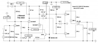
That is what is here in this example of the common Mullard circuit. The simulation has many less parts than seen lately here in DIY examples. All the tubes used can be found in many Mullard amplifiers. This simplified simulation establishes DC operating conditions. And makes adjustments much simpler.
This piece is not meant for the many established ‘experts’ out there. Just something that could make life easier for a few.
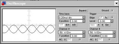
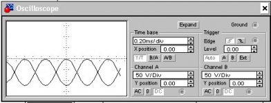
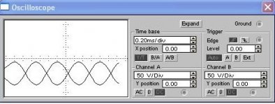
And have a look at those numbers. 25W from PP triodes & not yet fully driven. Refer to the scope trace of the grid(s) drive. Not quite to clipping. UL or pentode connected would be a lot more audio.
At DC the frequency is zero, all capacitance's become open circuits. And all the inductance's become a piece of wire of a few ohms resistance.
At DC most common pentodes used for audio look like they would if simply triode connected so far as currents & voltages are concerned. Even when the pentode plate is at a potential significantly higher, the DC currents don’t change much. That is a property of a pentode. This short cut will not work as well with TV Sweep Pentodes.
Based on these premises, why not simulate a triode version of the amplifier as a start, using ordinary triode models?
The full loop NFB is left until later. Gain & Phase of the simulation will provide guidance on that.
That is what is here in this example of the common Mullard circuit. The simulation has many less parts than seen lately here in DIY examples. All the tubes used can be found in many Mullard amplifiers. This simplified simulation establishes DC operating conditions. And makes adjustments much simpler.
This piece is not meant for the many established ‘experts’ out there. Just something that could make life easier for a few.
And have a look at those numbers. 25W from PP triodes & not yet fully driven. Refer to the scope trace of the grid(s) drive. Not quite to clipping. UL or pentode connected would be a lot more audio.
Attachments
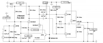
For the curious & others here are two more iterations of the Mullard 5 20.
All constructed from the original simulatio, just a few parts changes.
All constructed from the original simulatio, just a few parts changes.