Good day,
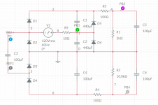
I have some 120VAC transformers I would like to put to good use. I need about +260V at circa 140mA, and -260V at circa 20mA. Doubling the 120VAC will do the job easily, but is it possible to also extract the -260V from it? One solution I came up with is shown in the schematic (done in multisim) + simulated output. C1 and C2 are 200V caps, C3...C6 are 450V.
what do you think? Any suggestions for improvements?
many thanks,
Erik
Attachments
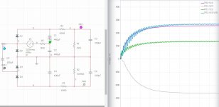
Looking back at my schematic, you can see that at the junction of the two 200V (doubler) caps the voltage is DC with a bit of ripple (look at the green line in the voltage graph). At the other hand of the transformer winding there is the 120Vrms swing, which is "sent" to the lower two diodes through C3.
So I do not think your schematic will work?
So I do not think your schematic will work?
It would work, but the split capacitor on the bottom is pointless, as the performance would be that of a half-wave doubler, with the disadvantage of the last capacitor taking all the stress. Nevertheless, that was supposed to be a joke. 🙂
HAHAHA, can't stop laughing about the joke. Hilarious. You don't see it on my smiley 😕, but on the inside, oh boy, rolling on the floor and tapping my belly, so funny!
any unloaded dc voltage developed drops big with load...
calculations are fine, but dummy load testing of the actual psu is better,
calculations are fine, but dummy load testing of the actual psu is better,
Thanks for the reply. I agree with you that dummy loading (or actual amp loading) will tell the complete picture. My aim with this thread is to avoid exploding capacitors, once that is good, I can do some actual loading on it.
build it and test it....i use the full wave voltage doublers all the time....easy to make power traffos...
Last edited:
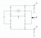
Perhaps think about protection for quirkier failure modes. Not saying there is an easy to see failure mode, but a reverse bias 1N4007 across the positive rail main caps would avoid any possibility of reverse biasing those caps (whether during power on or off or a fault).
IME full wave doublers when designed right never failed....and if you did it right the first time will work for ages....
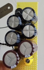
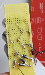
I was able to test the PS, drawing circa 70mA from the +250V and 18mA from the -250V (about half of the target current). It worked nicely, voltage drop in line with the calculated reactance of the cap. So I am happy. For anyone else reading: the voltage of the negative rail can be significantly reduced with a smaller C3 cap (higher reactance at mains frequency). This is recommended only when drawing a (relatively) constant current is needed from the negative rail.
Of course always willing to prevent exploding caps, so, what you recommend would be something like this? The positive side of this PS could be nicely wired P2P with an inline diode bridge.
Of course always willing to prevent exploding caps, so, what you recommend would be something like this? The positive side of this PS could be nicely wired P2P with an inline diode bridge.
Attachments
- Home
- Amplifiers
- Power Supplies
- Doubler PS sanity check