I've got my hands on a TA-5650 with known issue of blowing the rectifier board fuses on power-up.
It appears to be unmolested other than the relay looks to have been tampered with and bunch of soldering on the wire wraps between the rectifier, power and amp boards. My plan is to pull the V-Fet's and unhook the power leads between the rectifier & power board to the amplifier board. Then, check the condition of the power board and rectifier board to specifications with the amplifier board safe from defects in the rectifier and power boards.
That said, any advice from someone that's worked on one of these as know causes of blowing both fuses (they might have just powered it up after years of not using)? Any ideas on identifying what would cause both fuses to blow or approaching fixing root cause?
I had my set not too long ago, however, it is a working set before I try to do some restoration work to it.
You may want to remove all those Vfets and keep them away for the moment.
And pull out the entire power supply unit and test on the bench, though not necessary, it will make your troubleshooting a lot easier, without endangering the rest of the boards in the chassis.

Posts lots of pictures and voltages so other members can help you along.
Good luck!
You may want to remove all those Vfets and keep them away for the moment.
And pull out the entire power supply unit and test on the bench, though not necessary, it will make your troubleshooting a lot easier, without endangering the rest of the boards in the chassis.

Posts lots of pictures and voltages so other members can help you along.
Good luck!
Welcome the the TA-5650 restoration club! You have chosen a great piece of Audio history to play with, and if successful you will be very happy with its sound.I've got my hands on a TA-5650 with known issue of blowing the rectifier board fuses on power-up.
It appears to be unmolested other than the relay looks to have been tampered with and bunch of soldering on the wire wraps between the rectifier, power and amp boards. My plan is to pull the V-Fet's and unhook the power leads between the rectifier & power board to the amplifier board. Then, check the condition of the power board and rectifier board to specifications with the amplifier board safe from defects in the rectifier and power boards.
That said, any advice from someone that's worked on one of these as know causes of blowing both fuses (they might have just powered it up after years of not using)? Any ideas on identifying what would cause both fuses to blow or approaching fixing root cause?
ok 1st things 1st.
pull the vfets, clean (I use wet wipes to remove the old thermal paste), and then use a DMM to check they are viable ( see service bulletin and manuals on HifiEngine on how to test them). If the read ok and are all the same ranking, wrap in tin foil and put in a safe place.
Download both copies of the service manual, the colour copy IS THE OLDER COPY AND IS SUPERSEDED BY THE BLURRY BW COPY. Use the BW copy for values and the colour copy for clarity. NOTE: SOME OF THE SCREEN PRINT POLARITY MARKINGS ON THE BOARDS ARE WRONG, DOUBLE CHECK WITH SCHEMATICS.
with vfets out, measure the supplies to Amp output GND to check for shorts. If ok, use dim bulb limiter and power up to measure all relevant test points and see if you have correlation.
it may be the main filter caps are short and need replacing.
read Andy’s thread of his 5650 resto. Swap the death diodes, do the PSU mod, replace electrolytics, check the Dutch SB and change as needed. Change the relay, swap in Foil caps in signal path (10uF/100v), clean boards etc… Then get ready to install the vfets and set bias (sweaty palm times).
good luck and ask questions. We also like to see lots of photos…
jonboylaw, thank you for writing with your recommendations!
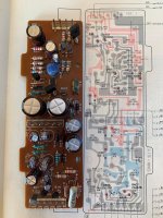
Definitely going to take your advice and I'm focused now on the power board and the rectifier board while disconnecting the amplifier board from the rectifier and power board and removing and testing the VFets. I've got both Peaks transistor and capacitor testers. As for the two power caps, they both tested at around what you see below in the image at 6800-7000uf and 1.22-1.28 olms and I plan on replacing them. I've made an order to Digi-key for lots of stuff and its arriving soon with some caps, resistor & diode mods, I'll have to investigate those foil caps you mentioned.
I've not pulled the VFets yet, and will pull them soon and hope they are still okay. I'll post some pictures along the way on this thread.
BTW, not sure what is "Dutch SB"?
The Dutch service bulletin, it is on HiFiEngine and ends in NL. It has a couple of component swaps and a revised bias setting for longevity.jonboylaw, thank you for writing with your recommendations!
Definitely going to take your advice and I'm focused now on the power board and the rectifier board while disconnecting the amplifier board from the rectifier and power board and removing and testing the VFets. I've got both Peaks transistor and capacitor testers. As for the two power caps, they both tested at around what you see below in the image at 6800-7000uf and 1.22-1.28 olms and I plan on replacing them. I've made an order to Digi-key for lots of stuff and its arriving soon with some caps, resistor & diode mods, I'll have to investigate those foil caps you mentioned.
I've not pulled the VFets yet, and will pull them soon and hope they are still okay. I'll post some pictures along the way on this thread.
BTW, not sure what is "Dutch SB"?
View attachment 1028920
Don’t bother with the transistor tester, they may not work with the vFets. Just look in the service bulletins (SB) on HFE and they show how to measure with a Digital Multi Meter.
also remember: NEVER USE A VARIAC TO BRING THE POWER UP WITH VFETS INSTALLED. The power supply is designed to come up in a certain way to ensure the vFets do not get damaged.
Have a look at Andy’s thread here: https://www.diyaudio.com/community/...aka-another-sony-ta-5650-v-fet-thread.379125/
J
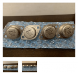
Bad news today as found that Q367; one of the 2SK60s' (HA-54) is testing bad after I pulled the VFet's today. So, it tested out where it should be a diode, it wasn't. Good news is the other 7 tested out good and I've got some of the parts in and started working on the power board.
S->D : .2 ohm
S->G : 89.4 ohm both ways
D->G : 9.3 ohms both ways
To do list:
One bad, seven good. Need a 2SK60 (HA-54)

Power Board: (partial done)

S->D : .2 ohm
S->G : 89.4 ohm both ways
D->G : 9.3 ohms both ways
To do list:
- Find one of these unobtainum's 2SK60 (HA54) over the internet.
- What component(s) blew the Q367?
One bad, seven good. Need a 2SK60 (HA-54)
Power Board: (partial done)
When sourcing the VFETs, the Chinese vendors are obviously a concern, many of them are fake or if they are genuine VFETs, they may not be the correct Ranking on them (most you see are 55 Ranking, which is likely to be faked). Best look for some genuine replacements, or possible 2 pairs of another Rank, so long as all are same rank by channel (Eg, L channel 54s, R Channel 57s).
There is a diode mod needed for D405 that is 2 1N4007 in series with centre tap to Gnd.
https://www.diyaudio.com/community/threads/sony-ta-5650-voltage-doubler-mod.298656/post-4871767
There is a diode mod needed for D405 that is 2 1N4007 in series with centre tap to Gnd.
https://www.diyaudio.com/community/threads/sony-ta-5650-voltage-doubler-mod.298656/post-4871767
Good news I scored an entire channel of 2SK60's / 2SK18's from Japan with the exact same ranking value I need. I pretty much have all the parts I need now to get this back together and do some testing.
As for the double diode fix, looks that you remove the existing D405 and replace it with 2 N4148's in series and then take the middle splice and route it to pin 5 on either the 6-pin headers. Can someone confirm this is the correct diodes and grounding the splice location?
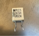
Maybe bad news, I was probing these R395, R396, R345, R346 are showing shorted out on my Fluke 175 meter. I guess .33K ohms is fine as long as these are not open as my meter won't read this low of an ohm value. Should I be concerned?
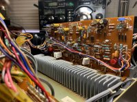
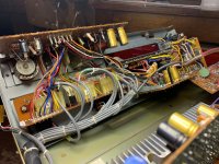
Open heart surgery on a TA-5650 :

As for the double diode fix, looks that you remove the existing D405 and replace it with 2 N4148's in series and then take the middle splice and route it to pin 5 on either the 6-pin headers. Can someone confirm this is the correct diodes and grounding the splice location?

Maybe bad news, I was probing these R395, R396, R345, R346 are showing shorted out on my Fluke 175 meter. I guess .33K ohms is fine as long as these are not open as my meter won't read this low of an ohm value. Should I be concerned?

Open heart surgery on a TA-5650 :


You are correct on the D405 point, you can connect the centre tap to any GND point that is convenient.
great that you managed to get a complete channel of VFETs, lucky score!
Why not put 100ohm in series with the 0.33 and measure, then remove the 0.33 and measure again to see if there is a difference? Will confirm resistors not short (they are unlikely to be short).
j
great that you managed to get a complete channel of VFETs, lucky score!
Why not put 100ohm in series with the 0.33 and measure, then remove the 0.33 and measure again to see if there is a difference? Will confirm resistors not short (they are unlikely to be short).
j
I'm ready to put back together the TA-5650 and have a question about testing the Power Board with it only connected to the rectifier board with the amplifier board removed from the chassis. Is this possible? My initial testing of the test points returned around 59v and nothing like what I expected. Should I be deep diving into the power board for a defect or is it only possible to test with all the connections in place because it does a soft start?
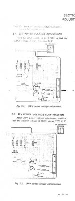
Test procedure : Can it be tested for 20 & 97v test points and adjusted with trimmer with only connecting the 6-pin connector in the center of the board? If not what's the safest method of testing short of connecting the amplifier board? Of course, I'll leave off the VFets.
Power Board:

Test procedure : Can it be tested for 20 & 97v test points and adjusted with trimmer with only connecting the 6-pin connector in the center of the board? If not what's the safest method of testing short of connecting the amplifier board? Of course, I'll leave off the VFets.

Power Board:
- Home
- Amplifiers
- Solid State
- TA-5650 Repair for 2022