Hello,
Still on my journey to recover long lost knowledge...
This time I am analyzing various circuits to understand how they are grounded.
Today, this one:

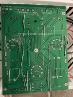
The plate under the PCB is metal.
Here is what I see:
Now, this design/build appears to be a newer version of this one:

This build seems to wire input signal ground.
Now, the other side of the board:

I see a star grounding pattern. And that center point connects to the bottom metal plate via a standoff.
Finally, the schematics:

My questions:
Also, if there is anything else that catches your attention in this circuit/build, please do share.
Still on my journey to recover long lost knowledge...
This time I am analyzing various circuits to understand how they are grounded.
Today, this one:
The plate under the PCB is metal.
Here is what I see:
- The IEC inlet ground tab is not wired to the metal plate.
- Input signal ground doesn't appear to be wired to the PCB.
- (unrelated to grounding) The headphone output jack appears to be wired to the preamp outputs.
- (unrelated to grounding) Input signal wiring bypasses the PCB.
Now, this design/build appears to be a newer version of this one:
This build seems to wire input signal ground.
Now, the other side of the board:
I see a star grounding pattern. And that center point connects to the bottom metal plate via a standoff.
Finally, the schematics:
My questions:
- Why should they not connect the IEC inlet ground tab to the bottom metal plate?
- How could they not connect the input signal ground to the PCB? (???)
- (unrelated to grounding) Is it OK to piggy back preamp out on the headphone out?
Also, if there is anything else that catches your attention in this circuit/build, please do share.
Attachments
Question one: Most people would say they should connect the metal plate to IEC ground.
Question two: They couldn't. It must be connected somewhere.
Question three: Yes, however some solid state inputs become low impedance when the device is turned off. Still, it shouldn't be much of a problem for a headphone amplifier.
Question two: They couldn't. It must be connected somewhere.
Question three: Yes, however some solid state inputs become low impedance when the device is turned off. Still, it shouldn't be much of a problem for a headphone amplifier.
If it is mounted with a 3-prong IEC socket, it is a Class I appliance, meaning that it must be earthed. But as I see the protective earth is not connected internally. This is against safety rules.
On the other hand, the PCB is connected to the metal chassis, and if you connect that to the mains protective earth AND if you connect the input signal ground to the PCB (as it should be), you most likely will get a ground loop.
Solution: connect the protective earth to the metal chassis to conform the safety regulations, connect the signal ground to the PCB, and isolate the PCB from the metal chassis. Bridge the two grounds with a Ground Loop Breaker. Search for it: it consists of a 35A diode bridge and a 10R resistor in special arrangement.
Question one: Most people would say they should connect the metal plate to IEC ground.
Question two: They couldn't. It must be connected somewhere.
Question three: Yes, however some solid state inputs become low impedance when the device is turned off. Still, it shouldn't be much of a problem for a headphone amplifier.
Thank you!
People who would not connect the IEC ground to the metal plate would do so to avoid a ground loop?
If it is mounted with a 3-prong IEC socket, it is a Class I appliance, meaning that it must be earthed. But as I see the protective earth is not connected internally. This is against safety rules.
On the other hand, the PCB is connected to the metal chassis, and if you connect that to the mains protective earth AND if you connect the input signal ground to the PCB (as it should be), you most likely will get a ground loop.
Solution: connect the protective earth to the metal chassis to conform the safety regulations, connect the signal ground to the PCB, and isolate the PCB from the metal chassis. Bridge the two grounds with a Ground Loop Breaker. Search for it: it consists of a 35A diode bridge and a 10R resistor in special arrangement.
Thank you!
I’ll look up that Ground Loop Breaker arrangement.