Hello all:
I am playing with this vintage amp that has 3 output transformers on the output stage. It is a small amp that sounds pretty nice for a desktop setup. As it is configured the center transformer sits behind a cap, that I believe is intended to filter out high frequencies for the center channel. The main problem I am having is that when the left and right channels are balanced, little to no sound reaches the center channel. If move the balance towards the left or right, you then get sound out of the center channel. I would not think that this is how it is supposed to work. My questions for the group follow.
1 - a resistor somewhere in circuit to cause more current flow into the center xfrmr when the balance is centered?
2- can I bridge the speaker outputs?
3 - can I replace the 3 xfrmrs with 2 bigger xfrmrs? If so, any suggestions on xfrmr specs?
4 - can I replace the 3 xfrmrs with 1 big xfrmr (mono configuration)?If so, any suggestions on xfrmr specs?
Thanks in advance for any help here.
I am playing with this vintage amp that has 3 output transformers on the output stage. It is a small amp that sounds pretty nice for a desktop setup. As it is configured the center transformer sits behind a cap, that I believe is intended to filter out high frequencies for the center channel. The main problem I am having is that when the left and right channels are balanced, little to no sound reaches the center channel. If move the balance towards the left or right, you then get sound out of the center channel. I would not think that this is how it is supposed to work. My questions for the group follow.
- Is the design such that it should work like this?
- If so, are there solutions that I can do to improve this?
1 - a resistor somewhere in circuit to cause more current flow into the center xfrmr when the balance is centered?
2- can I bridge the speaker outputs?
3 - can I replace the 3 xfrmrs with 2 bigger xfrmrs? If so, any suggestions on xfrmr specs?
4 - can I replace the 3 xfrmrs with 1 big xfrmr (mono configuration)?If so, any suggestions on xfrmr specs?
Thanks in advance for any help here.
Attachments
Welcome.
https://www.radiomuseum.org/forum/grundig_3_channel_stereo.html
An explanation is on the site that you lifted the schematic from. The key part: a specially configured phono cartridge.when the left and right channels are balanced
https://www.radiomuseum.org/forum/grundig_3_channel_stereo.html
@PRR - Thanks so much for your quick reply. I can somewhat see how the phase inversion at the cartridge would improve the bass channel. The problem now is that I am not using a phono as the source, I am using a 3.5mm aux connector to my source. As the L and R share a common ground, do I have any options to accomplish the phase inversion?
Also, in having one channel inverted, would that not cause cancelleation of the left and right channels?
yes - invert one input and also the corresponding loudspeaker connection and you should have no total inversion.
but it was just a wild guess. 🤐
but it was just a wild guess. 🤐
A careful look at the schematic reveals that the OPT secondaries are wired out of phase in the original application. This allows the bass to add instead of cancelling in the middle OPT. The easiest way to preserve this action is to invert one of the channels at the input with a small 1:1 transformer. If I were doing this I would use a pair of identical transformers with one having its secondary leads swapped. This way both channels are identical.
If the three outputs are not needed you could just use a pair of OPT's, one per channel to connect a pair of speakers in the normal fashion. You could also try shorting or resistively loading the output of the center channel, but this would only work if the original left and right OPT's are large enough to pass the intend program material without saturation.
If the three outputs are not needed you could just use a pair of OPT's, one per channel to connect a pair of speakers in the normal fashion. You could also try shorting or resistively loading the output of the center channel, but this would only work if the original left and right OPT's are large enough to pass the intend program material without saturation.
You could just dump that transformer, connect the two stereo SE transformers each directly to B+. 212V drops to 200 at the OPT plates through both transformers; it probably wouldnt come up that much if the "middle" transformer were simply removed from the circuit. You could always adjust R29, R28 a smidge to get the schematic voltages exact - but they're probably not single digit exact anyway.
If you still want an ambient center channel, you could connect a 3rd speaker from one of the OPT "+" to ground, because the OPTs are wired out of phase. Hopefully you already discovered this and wired one of the main speakers inverted to make it sound right. As this amp has no feedback from the tranny secondaries, you could also swap back one of the secondary connections so each stereo speaker at least wires up identically.
Sometimes these vintage manufacturers really went out of their way to make sure someone in the future had a hard time understanding just what it was they were trying to do. The Zenith 7F31, for example, looks like a good candidate for restore - until you find out that the bizarre OPT secondary winding configuration makes that amp useless - unless you replace the OPTs - the most expensive thing to have to do, besides re-tube it.
I bet a Hammond #125CSE would replace your current OPTs, if you want to sink another $100 plus ship into it. Perhaps get it straightened out first, back to an ordinary circuit - and give it a listen as-is - it might sound pretty good!
I like the L & R speaker sockets.
Imaging listening to headphones with the bass coming from the centre speaker!
I guess Tubelab is referring to something like this?
https://cpc.farnell.com/triad-magne...PING&s_kwcid=AL!5616!3!490691434445!!!network}!370085954770!&gclid=EAIaIQobChMItYXEgL-H9gIVV-vtCh0wjwsCEAQYAyABEgIzLPD_BwE
Imaging listening to headphones with the bass coming from the centre speaker!
I guess Tubelab is referring to something like this?
https://cpc.farnell.com/triad-magne...PING&s_kwcid=AL!5616!3!490691434445!!!network}!370085954770!&gclid=EAIaIQobChMItYXEgL-H9gIVV-vtCh0wjwsCEAQYAyABEgIzLPD_BwE
That circuit is very different than what we usually see driving the center channel speaker at the OPT, tapped secondaries.
But looks like it works with the proper source.
But looks like it works with the proper source.
Thank you all for the input here. I am learning a lot.
@Tubelab_com - Perhaps the output phase being out of phase is what corrects the input at the cartridge being wired out of phase. I remain perplexed as to why the center channel is silent when the balance is on center.
@ jjasniew - I am intrigued with the setup and found some nice efficient 4ohm speakers that match the tiny OPTs well. I really like to sound of the bass. Unfortunately, the balance has to be off center to enjoy it. As for the replacement of the 3 OPTs with two,
- could us use 2 $6.98 70V 15W Line Matching Transformer from part express?
If so, is this the wiring that you are referring to? (see attachment)
@ russc - I agree on 2 channels being nicer than 3 for serious listening. This project is more about nice ambient music at low volume with a small footprint.
Attachments

Those may work, but I have never used them. I was thinking of something like the Edcor PC10K/10K which I have used for a phase inverter in vacuum tube applications. Any of the small Edcor line matching transformers will work depending on the ability of your source to drive them.I guess Tubelab is referring to something like this?
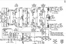
When used as intended the two channels are out of phase coming from the phono cartridge. They remain out of phase all the way to the OPT's. There are three OPT's, two single ended OPT's, one for each channel, and a push pull OPT wired across each channel, so it sees the proper out of phase signals. Assuming the top channel is of "normal phase," part of its output goes to the SE OPT and to its associated speaker. Note that pin 1 of the secondary is grounded and a "normal phase" signal is sent to the speaker. Part of that signal is sent to the P-P OPT, so its top half winding sees the "normal phase." The bottom channel is driven with an "inverted phase" signal from the phono pickup. Part of its signal goes to the SE OPT, but this OPT has its secondary windings reversed with pin 2 grounded so that the phase is inverted again resulting in a "normal phase" signal being fed to the speaker. The part of its signal that goes to the P-P OPT is already inverted so that no phase inverter is needed for proper operation of the OPT.@Tubelab_com - Perhaps the output phase being out of phase is what corrects the input at the cartridge being wired out of phase. I remain perplexed as to why the center channel is silent when the balance is on center.
Other vendors also used a similar system to get three channels from a two channel amp. Motorola was one.
When you drive this amp with two signals having "normal phase" the relationship needed for this parts count reduction system to function falls apart. Now both sides of the P-P OPT get "normal phase" signals resulting in cancellation of all the identical sounds, mostly the bass and anything placed in the center of the stereo sound field. The OPT in the lower channel has its secondary wires reversed so that the two SE based outputs will be out of phase. When the balance control is centered the signals are nearly identical, so maximum cancellation occurs in the P-P OPT. As it gets rotated in either direction the two channels are of different amplitude resulting in less than perfect cancellation.
Your wiring is what I had imagined doing. However, it's known that the 70V matching transformers dont hold up to Single Ended circuits, because of the quiescent current in the primary winding - something that's more or less counter balanced in a P-P design.- could us use 2 $6.98 70V 15W Line Matching Transformer from part express?
If so, is this the wiring that you are referring to? (see attachment)
A trick that may work is to use a 10K resistor (of adequate power rating) from the tube plate to B+ - then capacitively couple from the plate to the matching transformer winding. This blocks the DC and would allow one to play with the line matching transformers in a reasonable way. Unsure how good a tube amplifier design that is, even though the SS class A guys use such DC blocking caps all the time... If it sounds good and works for your desk setup, then why not?
Use as intended - the best solution is not to use input transformers to swap phase but just build a standard phase inverter as used in driving the finals in a PP amplifier. As it is low level it could even be done in solid state.
The original intended use required being driven by a specially made phono cartridge with the two outputs out of phase. The OP stated that he wants to use a "3.5 mm source." This will require something in one channel that inverts the phase. In order to preserve symmetry, phase and other parameters that may, or may not matter in this application, I suggested one of several possible ways to pus two identical "things" in the input path with the requirement that one "thing" inverts and one does not. The transformer is the simplest, and even a budget Edcor is probably less sonically intrusive than the rest of the amp.Use as intended - the best solution is not to use input transformers to swap phase but just build a standard phase inverter as used in driving the finals in a PP amplifier. As it is low level it could even be done in solid state.
Of course, there are several other ways to do this ranging from simple (one mosfet) to complex (opamp based instrumentation amplifiers or vacuum tube based LTP's). I suggested the Edcor transformer that I have personally used for driving a pair of SE tube amps out of phase into a P-P OPT for testing, an application similar to this without the third channel. When I actually built this, I used a split load phase inverter. Despite my user name, the circuit on my breadboard uses an LND150 mosfet for this task. A split load phase inverter requires an equal load on each output in order to work correctly. My application used both outputs, where this application would use one different output for each channel. The skill level of the OP is not known, so I suggested the simple foolproof transformer.
As stated above, a line matching transformer can be used for a push pull amp, and I do have a $5 Parts-Express 70 volt transformer in my 4 watt push pull guitar amp. They do not work well at all in SE applications unless the DC is blocked.
My bad, had not considered the skill level.The transformer is the simplest, and even a budget Edcor is probably less sonically intrusive than the rest of the amp.
The skill level of the OP is not known, so I suggested the simple foolproof transformer.
As stated above, a line matching transformer can be used for a push pull amp, and I do have a $5 Parts-Express 70 volt transformer in my 4 watt push pull guitar amp.
I'd only been thinking of what I had in my junk box what could do the job since certain parts have to be shipped in from overseas and due to the pandemic shipping is disrupted.
When I posted my reply I had considered a TI DRV134 balanced line driver.
But consider that this tube circuit cannot supply the operating voltages so with the added complexity of a split power supply the transformer is the simplest and cheapest option.
If Toobie were to reveal his location then part recommendations could have more relevance.
Edcor no longer ship to Europe.
If the source can drive about 500 Ohms: there is a $15-$20 audio isolation transformer, probably available in any land which has cars with souped-up sound systems, which is actually very good for the price. (As George is hinting: whole lot better than a 1959 console amp based on a cunning cost-cutting plan.)

The "15 Amps" is utterly bogus- these guys don't know what they are selling. The four RCA connectors show this is an audio toy. It is two 1:1 transformers, fairly low impedance, but workable in small studio or some hi-fi.
Get a small blunt tool and work the bushings into the can. Feel the can- it has a joint in the center, under and held-by the label. Knife the label and gently work the two halves apart. Two transformers on a PCB. The can is also good shielding, so I would bring out good wires marked for phase and tape it up again. For THIS oddball amplifier, flip phase (reverse the wires) on one channel.
All:
Many thanks for all the input here.
I went back to the circuit and found the center cap was bad. I also found that the rectifier tube was very week. By replacing the two, I got it to work as intended. The sound is really nice and I accomplished building a nice small unit for my office. As for inverting, I found that I only had to invert one of the output speaker channels. That is, I did nothing to the source.
@Tubelab_com - thank you for taking the time to explain the function of the circuit. Although some of it went over my head, I will use it as a basis of further study.
- Home
- Amplifiers
- Tubes / Valves
- Cannot Understand a Vintage Center Channel Amp Output Configuration