Question on TL594.
Pins 9&10 go to the amp's PS drivers, but pins 8&11 are connected to ground. Shouldn't 8&11 be connected to +12?
Someone modified the PS drive circuit of this amp. IRF3205 in the PS, PNP/NPN PS drivers. I dont see the drivers connected to +12v either. Both 8&11, and driver transistors are connected on the same trace with a PINK/PURPLE wire soldered back to Ground terminal. I think thats wrong.
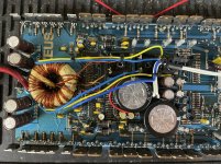
Also this amp is using large un-synced TO247 rectifiers instead of the a square & round ones usually found in these amps. The two large square rectifiers are in-tact, but usually these amps have a smaller round one. Photos next.
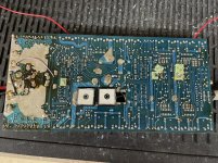
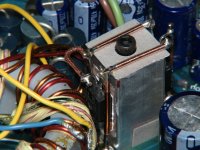
Board has been repaired before. Looks poor to me. Board condition is poor. Notice heat under transformer. Heat under PS fets. Lots of broken via/pads. I may just move the purple wire and return to owner if that 'works'.
Pins 9&10 go to the amp's PS drivers, but pins 8&11 are connected to ground. Shouldn't 8&11 be connected to +12?
Someone modified the PS drive circuit of this amp. IRF3205 in the PS, PNP/NPN PS drivers. I dont see the drivers connected to +12v either. Both 8&11, and driver transistors are connected on the same trace with a PINK/PURPLE wire soldered back to Ground terminal. I think thats wrong.
Also this amp is using large un-synced TO247 rectifiers instead of the a square & round ones usually found in these amps. The two large square rectifiers are in-tact, but usually these amps have a smaller round one. Photos next.
Board has been repaired before. Looks poor to me. Board condition is poor. Notice heat under transformer. Heat under PS fets. Lots of broken via/pads. I may just move the purple wire and return to owner if that 'works'.
Last edited:
What does the collector of the NPN driver connect to?
It appears that the drivers are soldered together on one set of pads. Is that true?
It appears that the drivers are soldered together on one set of pads. Is that true?
What does the collector of the NPN driver connect to? Should be B+ if the drivers are in an emitter follower pair configuration.
What does the collector of the PNP driver connect to? Should be ground.
It appears that the drivers are soldered together on one set of pads. Is that true?
What does the collector of the PNP driver connect to? Should be ground.
It appears that the drivers are soldered together on one set of pads. Is that true?
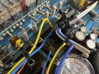
Yes the driver's are soldered in a 2/3 pair. NPN and PNP collectors are both connected to ground (Pink wire). NPN collector, and pin 8&11 of the TL594 are connected. Seems the legs of these drivers are correct, only down-way the collector is mis-connected via wire.
The pink wire seems to have been moved or mis-placed by just 1/4" under the PS cap. You can see a PS cap pad in the photo that close to the pink wire. That pad would have +12v
The pink wire seems to have been moved or mis-placed by just 1/4" under the PS cap. You can see a PS cap pad in the photo that close to the pink wire. That pad would have +12v
If you move the wire, will the connection be as described above?
Which driver is soldered into the pads? The center pad should b B+.
What's the part number printed for the driver pads?
Which driver is soldered into the pads? The center pad should b B+.
What's the part number printed for the driver pads?
I moved the pink wire. Seems amp is working perfectly now. NPN/PNP drivers are connected correctly. So, whomever may have been in this amp prior missed that one connect. Everything in the amp seems to be working now.
Are you going to leave the rectifiers as they are?
Contact MOER to see what he thinks about the rectifier mod. I wouldn't expect them to survive with no heatsink.
Contact MOER to see what he thinks about the rectifier mod. I wouldn't expect them to survive with no heatsink.
Those rectifiers are handling the +-18v rail in the Vari-drive circuitry. Im thinking they'll probably fail unless I sync them somehow. I can certainly test if they'll heat up under load if I cannot find replacements. Do you know if there is a high speed replacement for the original 16mm X 16mm square bridge rectifier? I see a lot of possible square versions but I dont know if ~8A is enough or if the speed would be a problem with something like from this list:
https://www.mouser.com/c/semiconduc...dge-rectifiers|~Mounting Style|~Length|~Width
https://www.mouser.com/c/semiconduc...dge-rectifiers|~Mounting Style|~Length|~Width
- Home
- General Interest
- Car Audio
- Hifonics Zues VI