Guys, hello.
I have NAD c326bee and I see some (as I think) very strange behavior of it.
Before trying to fix it myself, I would like to get some opinions.
The amp has huge heatsink with 4 main transistors on it (2 per channel).
Besides that it has 8 additional small heatsinks (4 per channel) with small transistor on each of them.
When amp is working the main heatsink is hardly warm,
4 of small heatsinks (2 from one channel and 2 from another channel) are warm ,
4 of small heatsinks (2 from one channel and 2 from another channel) are very very hot.
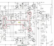
From now lets talk about one of channels. Look at scheme below.
Cold small transistors are Q346, Q350.
Very hot small transistors are Q342, Q344.
I replaced to absolutely new both zeners D322 D323 and both capacitors C361, C362.
My thoughts on a problem.
What causes heating of transistors? High current that flows through them, right?
What dictates the current value through Q342, Q344?
As I understand diodes D324, D325, D326, D327 are responsible for value of current that flows through Q342, Q344.
Probably these diodes became very tired and they allow higher current to flow through Q342, Q344.
So, as a start I want to replace these diodes.
Am I going in correct direction? What else can cause such heating? Maybe transistors themselves got tired?
Anything else?
Isn't it strange that big heatsink stays cold? Looks like amp is working mostly on small transistors..
I attach here full service manual with complete scheme.
I have NAD c326bee and I see some (as I think) very strange behavior of it.
Before trying to fix it myself, I would like to get some opinions.
The amp has huge heatsink with 4 main transistors on it (2 per channel).
Besides that it has 8 additional small heatsinks (4 per channel) with small transistor on each of them.
When amp is working the main heatsink is hardly warm,
4 of small heatsinks (2 from one channel and 2 from another channel) are warm ,
4 of small heatsinks (2 from one channel and 2 from another channel) are very very hot.
From now lets talk about one of channels. Look at scheme below.
Cold small transistors are Q346, Q350.
Very hot small transistors are Q342, Q344.
I replaced to absolutely new both zeners D322 D323 and both capacitors C361, C362.
My thoughts on a problem.
What causes heating of transistors? High current that flows through them, right?
What dictates the current value through Q342, Q344?
As I understand diodes D324, D325, D326, D327 are responsible for value of current that flows through Q342, Q344.
Probably these diodes became very tired and they allow higher current to flow through Q342, Q344.
So, as a start I want to replace these diodes.
Am I going in correct direction? What else can cause such heating? Maybe transistors themselves got tired?
Anything else?
Isn't it strange that big heatsink stays cold? Looks like amp is working mostly on small transistors..
I attach here full service manual with complete scheme.
Attachments
I checked the spec of these diodes.
They are specified in service manual as "SMD DIODE LL4148 SOD80 (VISHAY)".
I bought 20 pieces of "LL4148 - SMD-Si-Diode 100V 150mA Minimelf" for possible replacement.
The spec of them is here:
https://www.vishay.com/docs/85557/ll4148.pdfIt says there for forward current F = 5 mA (our case as I understand) it should give forward voltage from 0.620 to 0.720.
I turned the unit on and run it for some 5 minutes then measured voltage drop on all pairs:
D324-D325: 1.025V
D326-D327: 1.250V
D124-D125: 1.243V
D126-D127: 1.248V
But on diode pairs from same model that stand aside from amp section (far from heat area) I see:
D320-D321: 1.295V
D120-D121: 1.305V
From this I conclude that at least one pair of diodes is not OK: D324-D325: 1.025V.
I measured voltage on both:
D324: 0.625V
D325: 0.390V
So the bad diode here (as I think) it is D325.
The rest of diodes are working on their minimum voltage values.
Question: can I say that as time of use passes the diode forward voltage tend to decrease?
Is this correct statement?
For now I will replace the D325 and will see what will happen.
But maybe other diodes need the replacement too.
Ok, we see that D325 is not OK and it possibly explains why we have extra heating of Q142, Q144 on one channel.
But what with hot Q342, Q344 on other channel? What is the source of their extra heating? Will see.
Last edited:
It is very likely that, at idle of soft music, the big transistors do little work. "Class B". However the smaller parts likely run full current at any level, "Class A".What causes heating of transistors? High current that flows through them, right?
What dictates the current value through Q342, Q344? .....
Isn't it strange that big heatsink stays cold? Looks like amp is working mostly on small transistors..
Rather than speculating the parts "get tired", measure! The diodes should show 0.6V to 0.7V voltage drop. Where two diodes bias a transistor with a 15r emitter resistor, you expect the resistor to drop the other 0.6V and so: 0.6V/15r= 0.040 Amps, 40mA. Assuming 40V across the transistor(??), that is 1.6 Watts. Depending on the size of a "small" heatsink, that may be mighty warm, even not.
PRR, thanks for your reply.
All diodes above measure the same with both probe positions (no difference).
I replaced two diodes (right channel):
D324: 0.625V
D325: 0.390V
After that voltage drop D324-D325: 1.305V.
But control of idle current on right channel became bad again - stuck on minimum 4.4mV instead of max 3.5mV allowed by service manual.
Besides that on cold I see no idle current flowing at all (it shows 0mV on TP3 and TP4 pins).
Also I see 0mV voltage drop on R441.
Will play with it to understand more.
Then suddenly I see that current starts to flow, showing 4.4mV minimum idle current.
When it is working like that I measured DC offset on both channels and saw that left channel has 1mV DC and right channel (problematic one) has 2mV DC offset.
So, when unit is turned on (for like 20-30 minutes) and volume on 0 with no input I measure following voltages:
The actual VDD and VCC is +-47.2 V and not 46V.
15 ohms resistors:
R441: 0.651V (right channel)
R435: 0.660V
R241: 0.660V (left channel)
R235: 0.660V
Zener diodes:
D322: 5.1 V
D323: 5.1 V
D122: 5.1 V
D123: 5.1 V
Small diodes:
D324-D325: 1.20V
D326-D327: 1.20V
D124-D125: 1.20V
D126-D127: 1.20V
56 ohms resistors:
R443: 0.554V
R437: 0.560V
R243: 0.579V
R237: 0.580V
Big 5W resistors
R440: 2.4mV
R439: 2.4mV
R240: 1.6mV
R239: 1.8mV
After some manipulations with configuring idle current on left (healthy) channel its stuck now on 3.3mv, does not go lower then this.
Very very strange.
I think maybe this instability caused by transistors Q142, Q144, Q342, Q344 that are "tired" and malfunctioning a bit?
Where all these random changes can come from?
Currently both channels run OK (from sound perspective), but Q142, Q144, Q342, Q344 are hot 🙁
It is very likely that, at idle of soft music, the big transistors do little work. "Class B". However the smaller parts likely run full current at any level, "Class A".
Rather than speculating the parts "get tired", measure! The diodes should show 0.6V to 0.7V voltage drop. Where two diodes bias a transistor with a 15r emitter resistor, you expect the resistor to drop the other 0.6V and so: 0.6V/15r= 0.040 Amps, 40mA. Assuming 40V across the transistor(??), that is 1.6 Watts. Depending on the size of a "small" heatsink, that may be mighty warm, even not.
PRR, thanks for your reply.
Heat sinks of these transistors are so hot, that I can not hold my hand on them more then 30 seconds.
I think I don't understand something basic in the schematics.
I don't understand idle current of what transistors we are trying to control here.
From measurements above we see that through 15ohm resistors flows current of 44mA (Q342, Q344 pairs of transistors).
And this current does not depend on any configurable parameters. Am I right?
And these Q342, Q344 are the hot transistors.
As I understand the trimpots control idle current that flows through Q350 and Q346. But they stay cold!
Could you explain it to me?
Last edited:
I repaired a C355BEE recently and noticed the same thing. The larger heatsink is cool at idle but most of the smaller ones were hot. Like you, I couldn't keep my finger on one for more than 30 seconds.
I believe it is normal as has been mentioned by another user. The temperature did not deviate over hours of testing and the amp was sounding great.
I believe it is normal as has been mentioned by another user. The temperature did not deviate over hours of testing and the amp was sounding great.