Hello!
I'm building an analog stereo amp that can be switched to bridged mode. i.e. a 4-channel amp with a switch on the back. Each channel shall have it's own DC offset speaker protection, so I'm looking at 2x stereo protection boards.
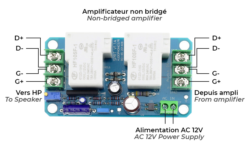
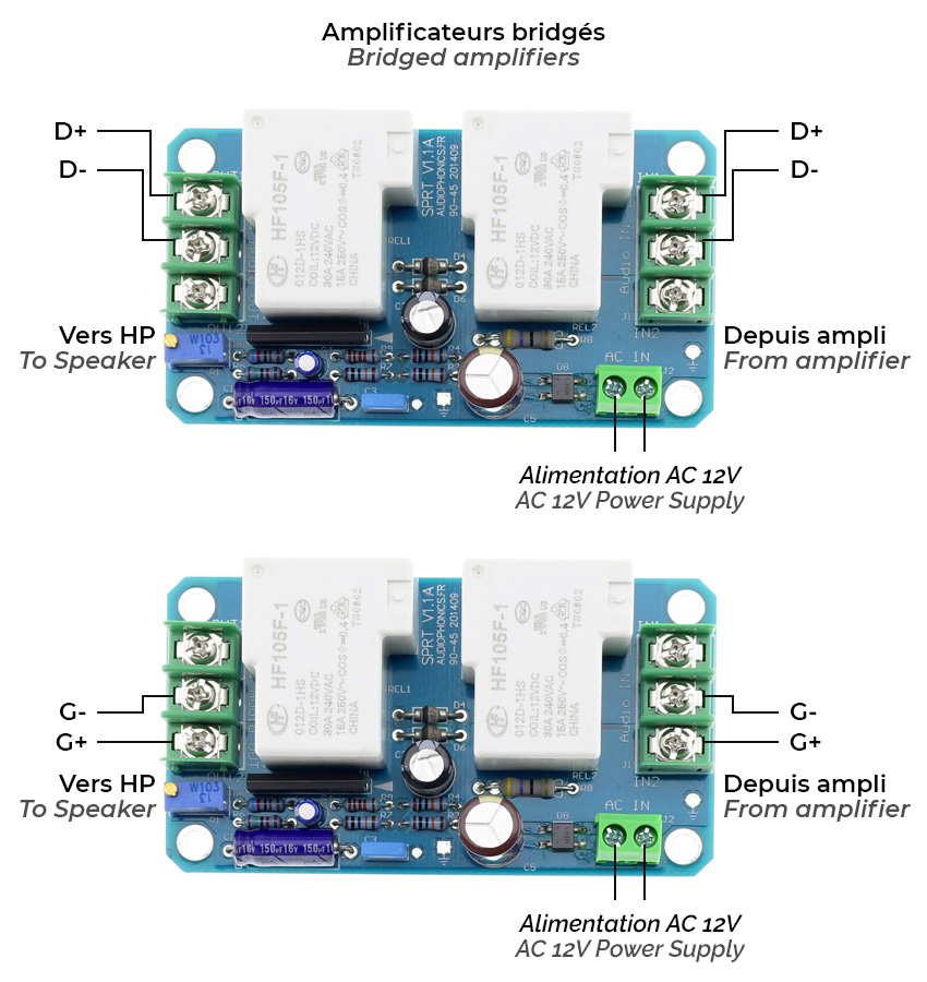
This protection board I'm looking at. They state "Stereo module for 2 channels. (not bridged because GND common)". I'm going to copy the shown wiring diagrams here:
This leaves me confused. It would force me to buy 4 instead of 2 boards. Why is the bridged setup different? Bridged amps share a power supply, so they share GND on the power input and speaker output anyway. I just don't use GND as a speaker output, that's all.
I'm assuming the module measures DC between
So what's up with only using half the module in a bridged setup?
Thanks a lot!
I'm building an analog stereo amp that can be switched to bridged mode. i.e. a 4-channel amp with a switch on the back. Each channel shall have it's own DC offset speaker protection, so I'm looking at 2x stereo protection boards.
This protection board I'm looking at. They state "Stereo module for 2 channels. (not bridged because GND common)". I'm going to copy the shown wiring diagrams here:
This leaves me confused. It would force me to buy 4 instead of 2 boards. Why is the bridged setup different? Bridged amps share a power supply, so they share GND on the power input and speaker output anyway. I just don't use GND as a speaker output, that's all.
I'm assuming the module measures DC between
D+/D- and G+/G-, and has the relays switch D+ and G+. In bridged mode, the speaker would plug in between D+ and G+. If one of the amps blows, a DC offset may appear between either D+/D-, or G+/G-, triggering the protection module and breaking the connection to the speakers.So what's up with only using half the module in a bridged setup?
Thanks a lot!
Last edited:
I found that the large rectangular IC is very likely a UPC1237. There's a typical application circuit in its datasheet which I copied below.
Pin 2 is the DC sense pin. Both speaker channels are connected to a capacitor through a resistor each. Any DC components on the speaker channels are going to charge the capacitor. Upon exceeding a treshold voltage, the IC switches off the relay.
I think I see the problem now for bridged scenarios. In the unlikely event that the "master" amp fails shorting +VCC onto its output, and simultaneously the "slave" amp fails shorting -VCC onto its output, both rails are going to cancel each other out, never charging the protection cap. This sucks.
However, when using this IC in a regular stereo setup, the same problem could theoretically happen. Maybe it's simply deemed too unlikely to be relevant?
Any thoughts? Thanks!
Guess I'm going to make my own protection circuit. Found this one which makes clever use of optocouplers and simple common components. I like. Adapting it to 4 channels shouldn't be hard, and I can use proper high-current relays.
I do disagree on the use of fuses within the signal path tho. Their thinking is they force the speaker onto GND to make the fuse blow and extinguish the arc in the relay. That doesn't seem very sensible to me...
I do disagree on the use of fuses within the signal path tho. Their thinking is they force the speaker onto GND to make the fuse blow and extinguish the arc in the relay. That doesn't seem very sensible to me...
The uPC1273 is sensing DC, with respect to ground, so you can use it for a bridged amp as shown. L & R being the two channels bridged or out of phase with each other.
IF one channel rails one polarity and the other channel the other polarity, the circuit might not work. i have seen them use slightly different sized resistors for the 56k, so the circuit would activate if such a situation happened.
IF one channel rails one polarity and the other channel the other polarity, the circuit might not work. i have seen them use slightly different sized resistors for the 56k, so the circuit would activate if such a situation happened.