I've been trying to incorporate an AB-Q for 4 tubes, PP & PPP & SE amps into my EL84 Baby Huey. Why? Because it's fun trying this stuff.
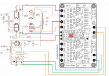
My 2 EL84 BH amp boards work perfectly with bias pots. With the bias servo wired-up as shown I've had no success.
With a single BH module and both EL84s installed, one EL84 goes straight through 30mA and on up to 100mA at which point I turn off. The other EL84 starts conducting and then turns off.
With a single EL84 installed, anode current plateaus at 125mA before I quickly turn it off. I can see the AB-Q trying to turn the bias back down on the gate of the MOSFET, but the source of the STU9HN65M2 doesn't follow it.
I'm starting to wonder whether either the use of MOSFET drivers or the CCS with the MOSFET drivers might not be compatible with the bias servo.
Can anyone give me any advice on this please?
Attachments

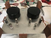
That is a very good looking amplifier!
Parallel tubes . . .
A word of advice, make the circuit so it sets the current separately for each tube.
That means, a separate bias circuit for each tube.
If after that, you still have problems with the currents, then you have an additional factor that is broken or incorrectly applied.
Some circuits do not lend themselves to separate bias circuits for each tube.
In that case, do not parallel the tubes, or modify the circuit from its original design to be able to work with parallel tubes.
Additionally, I personally will never use a "bias servo" circuit.
Some circuits can be improved, and some circuits can only be made worse.
All circuits have some kind of tradeoff(s).
If you do not like individual adjustable fixed bias, then try individual self bias resistors and bypass capacitors (if your circuits can do that).
Then increase the B+ by the amount equal to the bias voltage, or give up a little of the output power.
Simplicity and Reliability count.
Complexity, and a prolonged "War" battling the circuit may, or may not, be worth it.
Just my personal opinions.
Last edited:
It is a push pull amp with 2 EL84s per channel (not parallel). Look at the schematic that he posted.
There are discussions and experiments with Pavel's boards on this site and a long thread on AudioKarma. The folks that implemented his boards have been pleased with the results especially those using toroidal outputs.
I am not sure how to wire it with your source followers. Contact Pavil. He has been very responsive (posting) on both sites that I mentioned and has helped with installations.
https://www.diyaudio.com/community/members/pavlikkkk.332780/
Steve
Last edited:
Sorry, the following statement below from Post # 1 caught my eye: "PPP" (Parallel Push Pull)
. . . "I've been trying to incorporate an AB-Q for 4 tubes, PP & PPP & SE amps into my EL84 Baby Huey."
As long as the bias is separate; one bias for the 'push' tube and another bias for the 'pull' tube, at least the primary halves will have the same current.
Push pull output transformers love balanced quiescent currents.
But unfortunately, the OP's problem remains.
Have you disconnected the 1 MOhm resistors from power driver mosfets' gates to biasing circuit on BH boards?
Otherwise the two bias circuits will interact.
On top of that, 100k is too low as a reference for mosfet gates and 1 MOhm is preferred not to add further load to the already heavy loaded phase splitter.
Otherwise the two bias circuits will interact.
On top of that, 100k is too low as a reference for mosfet gates and 1 MOhm is preferred not to add further load to the already heavy loaded phase splitter.
Thanks. The instructions for the AB-Q module require 100k to 200k in this position. I've checked the earthing several times and it also is as per the instructions.
Please check if the 100k requirement is due to the bias circuit itself or (more probably) due to tube requirements: 100k will waste the performance of the phase splitter reducing its gain and increasing its distortion.
Pavil is currently posting on this thread https://www.diyaudio.com/community/...g-auto-bias-for-tube-amplifiers.380699/page-2
This is when I have to eat humble pie and admit an embarrassing mistake 😕. It's not the first time and it won't be the last.
I had the GRD inputs from the AB-Q connected to a different tube from the CATH outputs to the AB-Q.
In my defence, despite having each EL84 cathode resistor adjacent to its EL84, whoever designed the EL84 BH amp boards had the bias pots on the opposite side of the board from the EL84s they were connected to. It's so long since I built and tested the boards with bias pots I'd forgotten.
Between the strangely located bias pot problem and the lack of a silkscreen on the bottom of the board making debugging extremely difficult when it's in a chassis with the tubes on the top, I'm sorely tempted to design my own boards.
I should have twigged when I first noted that the sources of the source followers weren't following the GRD inputs. The mistake has cost me a couple of weeks and a lot of frustration. 😢.
Anyway, I can report that the AB-Q bias servo works perfectly with the Baby Huey amp boards. When I test my second board I'll try replacing the 150k AB-Q isolation resistors with 1M ones.
I tried replacing the 150K resistors with 1M ones and there was no increase in performance. If anything, there might have been a slight decrease in gain.Please check if the 100k requirement is due to the bias circuit itself or (more probably) due to tube requirements: 100k will waste the performance of the phase splitter reducing its gain and increasing its distortion.
Maybe with traditional biasing the 1M resistors improve performance but that doesn't seem to be the case with this bias servo.
- Home
- Amplifiers
- Tubes / Valves
- Bias servo with EL84 Baby Huey?