Analysis and study of amplifier stability.
The issue of instability arises when an inverting signal becomes such that it helps the input to cause more change in the output. An inverting signal should always work in opposition with the non-inverting input, so that, the differential input or equivalent, work like a balance with as little offset as possible depending on amplifier open loop gain. The output is guaranteed to mimic the non-inverting input in shape as long as the inverting inputs continues opposing the input. However, electric current and voltage may not be in phase. This difference arises everywhere, as it depends on inductance and capacitance. The latter are distributed properties which cannot be completely eliminated as they are a direct consequence of Physics, namely Electrostatics, Electromagnetism and Electromagnetic Induction. When the condition of opposition is not satisfied, both inputs start helping each other breaking the very condition for which a differential input is designed: that of stealing current from each other! Yes, if A + B = constant, where A and B are currents, if A increases, B must decrease by the same amount, and vice versa. When both an inverting input and non-inverting input work to aid or break an output, more output will cause even more, and the amplifier ends up with self oscillation blessed with intermodulation due to the input stage not behaving linearly. Then non linearity is caused by breaking the condition of A + B = constant. A current source at the head of an input stage supplies stable current, but it cannot keep the input pair from conducting less current and cannot supply more, so the input stage may find itself saturating and preventing the current source from supply its designed current. All this mess leads to the generation of harmonics which continue to mix the broth to such an entent, that one gets horrible looking wavetrains only the worst of nightmares can produce. Therefore, it make a lot of sense to look at the phases of currents to the bases of the differential input pair. Current is what drives the transistors (BJTs). Yes, they are theoretically driven by voltage but without a base current there is no collector current apart from minute leakages. In our study we can make two charts one with the Miller capacitor an one without it. This helps us compare with an amplifier that is known to be oscillating vigorously.
I will use my amplifier as an enxample, reader can choose other circuits. This analysis should put things into perspective and be more logically accessible to many.
Please, refer to the attached graph images in the following discussion.
To study amplifier stability we are interested in frequency response until the closed loop gain becomes 1. In other words, 0dB. Gains below 1 will not produce sustained oscillations.
The AC analysis of the output is done with the input being exactly 1V peak to zero. This allows the charting algorithm to plot the actual gain of the amplifier against frequency.
The discussion will follow in the next post.
Attachments

Last edited:
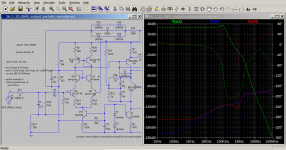
Looking at the AC chart with the Miller Capacitance not active, we notice that at 420kHz the gain is unity. We will stop at this frequency as this is the topmost frequency for which sustained oscillations can initiate themselves. Other frequencies can still be generated through other means like non-linearity and inter-modulation.
Let us look at the chart more closely and write down some values to put things into perspective: (II = inverting input; NII = non-inverting input)
The table above clearly illustrates that the inverting input current become non-inverting at about 3kHz. Such a low frequency would force the amplifier to generate intermodulation due to input stage saturating and undersaturating. The current mirror's status of control is completely lost due to the input stage not obeying the rule that currents in II + NII = constant. We have simply an frenzied input stage doing things it should not do!
Now, we will do the same exercise with the Miller Capacitor introduced. The amplifier should become stable and the behaviour of the input stage should become predictable and ordered.
[To be continued... We will need more study to understand what is happening.]
Let us look at the chart more closely and write down some values to put things into perspective: (II = inverting input; NII = non-inverting input)
Code:
Freq/Hz     II phase     NII phase
10             10             -120
100            2              -200
1.0k           21             -260
3.0k           48             -268
14.7k          70             -280
138.4k         34.7           -333
424k           22             -353
The table above clearly illustrates that the inverting input current become non-inverting at about 3kHz. Such a low frequency would force the amplifier to generate intermodulation due to input stage saturating and undersaturating. The current mirror's status of control is completely lost due to the input stage not obeying the rule that currents in II + NII = constant. We have simply an frenzied input stage doing things it should not do!
Now, we will do the same exercise with the Miller Capacitor introduced. The amplifier should become stable and the behaviour of the input stage should become predictable and ordered.
[To be continued... We will need more study to understand what is happening.]
Last edited:
Please, note the headings of the preceding table in the previous post for the inputs are wrong: they are interchanged. The low phase is for the NII.
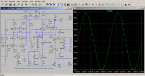
The following is the table with the Miller Capacitor introduced. The behaviour is much more ordinal as can be seen from the graph and from the table.
It can be clearly seen that until the gain drops to unity, the behaviour of the differential pair is well defined and stable. The phase difference of the current is not enough to cause oscillations and bad behaviour on the part of the input stage.
The following is the table with the Miller Capacitor introduced. The behaviour is much more ordinal as can be seen from the graph and from the table.
Code:
Freq/Hz      NII          II
10           8.4        -119
100          6.0        -140
507          25.4       -113
1.51k        55.7        -98.4
3.07k        70.3        -93.5
7.90k        78.8        -91.1
12.3k        78.8        -89.9
37.8         71.5        -87.5
165.2        50.8        -98.4
424.8        54.5        -106.9 {unity gain reached}
It can be clearly seen that until the gain drops to unity, the behaviour of the differential pair is well defined and stable. The phase difference of the current is not enough to cause oscillations and bad behaviour on the part of the input stage.
To Moderators:
Please, edit post number 2. The headings in the table for the values of the inverting input II, and non-inverting input NII are interchanged. The second column should be headed by NII, while the third should be headed by II.
I would be interesting to actually capture the input stage misbehaving while the amplifier is unstable. In this post I will try to find evidence using LTSpice that this is actually happening. Let us try. 🙂
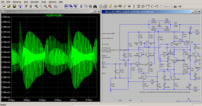
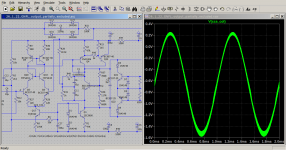
Looking at output.png it is clear that this amplifier is extremely well behaved. However, the transient analysis took much much longer than usual indicating some form of severe self oscillation that is not immediately evident in this graph.
Now, let us see what is happening to the collector currents of the differential pair. This is where the symptoms of the absence of the Miller capacitor are. Although, there are severe self oscillations, the input stage is still behaving in some form of control. The pair's transistors seem to be obeying the condition of A + B = constant. Let us delve more, maybe, we can find somewhere where A + B = constant is not respected! Looking at the third chart showing the constant current source collector voltage, it is again clear that there is no such misbehaviour. This amplifier seems to hold onto its task notwithstanding of the tempest of self oscillations taking place in its input stage. I am sure, but still stand to be corrected, that if we design a very bad amplifier we should be able to find instances where A + B = constant is not held.
Please, edit post number 2. The headings in the table for the values of the inverting input II, and non-inverting input NII are interchanged. The second column should be headed by NII, while the third should be headed by II.
I would be interesting to actually capture the input stage misbehaving while the amplifier is unstable. In this post I will try to find evidence using LTSpice that this is actually happening. Let us try. 🙂
Looking at output.png it is clear that this amplifier is extremely well behaved. However, the transient analysis took much much longer than usual indicating some form of severe self oscillation that is not immediately evident in this graph.
Now, let us see what is happening to the collector currents of the differential pair. This is where the symptoms of the absence of the Miller capacitor are. Although, there are severe self oscillations, the input stage is still behaving in some form of control. The pair's transistors seem to be obeying the condition of A + B = constant. Let us delve more, maybe, we can find somewhere where A + B = constant is not respected! Looking at the third chart showing the constant current source collector voltage, it is again clear that there is no such misbehaviour. This amplifier seems to hold onto its task notwithstanding of the tempest of self oscillations taking place in its input stage. I am sure, but still stand to be corrected, that if we design a very bad amplifier we should be able to find instances where A + B = constant is not held.
Attachments
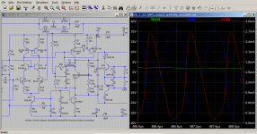
In this post I will explore the sum of the collector currents of the differential pair transistors whe the Miller Capacitor is removed. As we have seen the amplifier still behaves unexpectedly nicely with an output much similar to what would be explected when the Miller Capacitor is connected. Such a condition puts stress on the input stage, especially when self oscillations take place without a band filter or a tuned circuit. Every component is left to roam without control. To see what is happening the condition A + B = constant, we will plot the sum of the collector currents and look at the results.
Looking at the chart the Ic(Q5) + Ic(Q6) varies between 2.856mA to 2.992mA. This indicates the current source is offering its high output impedance successfully and therefore, it is never losing control. It also sheds important light onto what the differential pair is doing and whether they are still in control. Since the sum total is maintained reasonably well, it is clear, the differential pair are in good control of the situation and the balance condition is holding and working.
It will be interesting if we explore what is being fed into the negative feedback two-pronged network. That should give some insight as to why the amplifier is succeeding not to go into a frenzy of vigorous self oscillations.