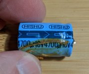
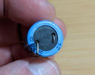
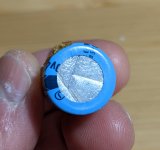
To me, the cap in the photos below looks like a plain jane electrolytic, however, I've seen some super caps for sale on Mouser that also look like electrolytics, rather than the round, button-shaped kind I'm used to seeing. The reason I ask is because the cap shown was in the part of the circuit for an NAD tuner that's responsible for remembering the station presets when the unit is powered off. In this application, I'd expect a super cap (or a coin battery), but this looks like a regular electrolytic and the parts list in the service manual just says "low leakage" in the note after the capacitance and voltage value. Another wrinkle: A different NAD tuner that uses the same IC does use a super cap in this role.


It's a standard electro. "Super caps" have capacities usually measured in Farads, not microFarads...
Yep, you're right--the capacitance is way too low. At the risk of veering too far from the "Parts" sub-forum purpose, my next question then is what would prevent a regular electrolytic from doing the job of powering the IC to remember the presets? Currently, the tuner doesn't hold them after powering off, and I've replaced the cap in question, as well as confirmed that the 4.9V that should be at pins 41 and 42 while powered on is there.
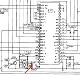
And the pointer in the schematic shows it as a standard power supply decoupling cap between Vdd and Gnd ...
Jan
Jan
C914 is the electrolytic I'm referring to. It's the cap for memory retention (CMOS RAM) in the IC.
I'm going to swap out Q909 in the event that it's defective and causing the voltage stored in C914 to leak away.
I'm going to swap out Q909 in the event that it's defective and causing the voltage stored in C914 to leak away.
I replaced Q909, but no change. The TC-9147P datasheet says it needs a minimum of 2V at pin 42 VDD for the CMOS RAM to retain the preset. I'm seeing the C914 cap drain to less than that within 15 minutes. I also checked that the Inhibit function (pin 40) was getting the 4.8V it requires, and it is.
I'm stumped.
I'm stumped.
Maybe the chip is damaged and drawing excess current on the CMOS RAM pin? In any case, if I understand the circuit properly, you could replace the 4700uF cap with a battery to extend the memory maybe?
I replaced C918, and now the memory seems to be working--I left the unit powered off overnight and the presets were retained in the morning.
No.. C918 that fixed the issue is 100nF isn't it? The 4700uF really looks like a PSU decoupling cap - at least in the schematic posted. OTOH, was that 100nF a short?
A short of C918 (which is actually a 0.047uF cap) would seem to be the only explanation, though it tested ok when I removed it. So it's certainly possible that something else I did, perhaps fixed a bad solder joint, actually corrected the issue.
As for the 4700uF, all I can tell you is that the datasheet for the IC specifies a battery or cap at pin 42 that supplies between 2V and 5.5V to maintain the CMOS RAM. It sure isn't any of the other caps there. . . .
As for the 4700uF, all I can tell you is that the datasheet for the IC specifies a battery or cap at pin 42 that supplies between 2V and 5.5V to maintain the CMOS RAM. It sure isn't any of the other caps there. . . .
- Home
- Design & Build
- Parts
- Is This a Super Cap?