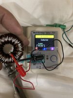
I need to rewrap the inductors on my Kicker 06zx750.1 class d monoblock car amp as the shielding on 1 has failed, 2nd doesn’t look too bad to where it would malfunction so I tested it on my cheap-o LCR tester and got a reading of .12mH and .32-.36ohms. Does that seem anywhere near right for this amps inductors?
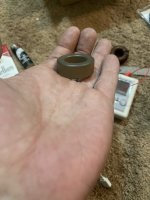
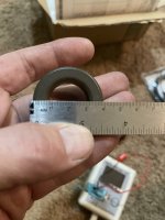
As far as the inductor itself it seems to be a brown(green on 1side) core that measures 40x23x15mm with what seems to be 10awg magnet wire (waiting for wire gauge feeler) it has 35 turns total, 20 1st wrap, 15 on 2nd wrap.
I guess I could just rewrap each core with appropriate length/size/turns of magnet wire and just be done with it, but would like to know what the inductors for this amp are supposed to test as so I can make sure it’s correct. Thx
Attachments
Toroid core need pay attention Rdc, Isat, L value.
But now more use of class D(MnZn core) and PQ core inductor in the car amp.
Thus with more high current and better appearance and no thermal aging problem if long time use.
But now more use of class D(MnZn core) and PQ core inductor in the car amp.
Thus with more high current and better appearance and no thermal aging problem if long time use.
Aren't the MnZn generally used for transformers, not output filter inductors?
For Tekjive, did you get a value for the inductor?
For Tekjive, did you get a value for the inductor?
Yes I did, from Bill himself too, spec is 135uH, he suggested just rewrapping the cores with same winding count to get similar uF, said it doesn’t have to be exact. I tried looking online for more info on inductors and if the ohm rating and amp rating are also as important but there is sparse info on output inductors online that I can find :/Aren't the MnZn generally used for transformers, not output filter inductors?
For Tekjive, did you get a value for the inductor?
I was contemplating just buying direct replacements instead of rewrapping my own but don’t know what other info I need to match spec wise, I usually see besides uF rating a lot have an Amp rating and a few others as well, but usually don’t tell you gauge of wire or number of wraps in data sheet.
If anyone had any more info on output inductors such as resistance rating and amp rating besides Henry rating, and if those ratings are important to the specs of an amp, I’d greatly appreciate it, trying to learn all I can as I go, and this seems pretty important to the class D setup. I did end up buying a spool of high temp 200’c magnet wire and just going to match the wraps, etc. last piece to this amp repair 🙂
Re-wrapping with the same cross section of copper and number of turns then confirming that the value is right, is often the best that you can do.
The study of magnetic components and their function can be very complex. If you have specific questions, I'll try to help but magnetics is nearly voodoo as far as much as I understand it.
The study of magnetic components and their function can be very complex. If you have specific questions, I'll try to help but magnetics is nearly voodoo as far as much as I understand it.

Ty Perry, now I know why some techs I’ve asked have stated they don’t do inductors, lol. Ya I think I’ll just rewrap til I get as close to 135uH as possible, just best bet 🙂 I would like to know if/what other specs are usually needed when output inductors are considered, but just a side query at this point as from here on out I’ll prolly just rewrap bad inductors with same wire gauge and number of wraps since it’s not an exact science like Bill was saying, close enough is good enough for me lol, but still would like to at least learn the common specs needed when replacing if rewrapping isn’t an option.
Not all inductors can be rewound. If you find one that got so hot that the board has thermal damage, the inductor's core material may have changed its properties.
The attached PDF file will likely be more than you want but reading over it will give you an idea of what's involved in designing an inductor.
The attached PDF file will likely be more than you want but reading over it will give you an idea of what's involved in designing an inductor.
Attachments
What's the current in your circuit? Fre. and Rdc ?Ty Perry, now I know why some techs I’ve asked have stated they don’t do inductors, lol. Ya I think I’ll just rewrap til I get as close to 135uH as possible, just best bet 🙂 I would like to know if/what other specs are usually needed when output inductors are considered, but just a side query at this point as from here on out I’ll prolly just rewrap bad inductors with same wire gauge and number of wraps since it’s not an exact science like Bill was saying, close enough is good enough for me lol, but still would like to at least learn the common specs needed when replacing if rewrapping isn’t an option.
Yes I did, from Bill himself too, spec is 135uH, he suggested just rewrapping the cores with same winding count to get similar uF, said it doesn’t have to be exact. I tried looking online for more info on inductors and if the ohm rating and amp rating are also as important but there is sparse info on output inductors online that I can find :/
I was contemplating just buying direct replacements instead of rewrapping my own but don’t know what other info I need to match spec wise, I usually see besides uF rating a lot have an Amp rating and a few others as well, but usually don’t tell you gauge of wire or number of wraps in data sheet.
If anyone had any more info on output inductors such as resistance rating and amp rating besides Henry rating, and if those ratings are important to the specs of an amp, I’d greatly appreciate it, trying to learn all I can as I go, and this seems pretty important to the class D setup. I did end up buying a spool of high temp 200’c magnet wire and just going to match the wraps, etc. last piece to this amp repair 🙂
"If anyone had any more info on output inductors such as resistance rating and amp rating besides Henry rating, and if those ratings are important to the specs of an amp, I’d greatly appreciate it"
RMS current ratings are power ratings for inductors, derived by applying DC or low-frequency AC current to measure the resultant temperature rise. This allows for an accurate determination of temperature rise vs. RMS current, which can easily be related to temperature rise vs. power loss: Power Loss = Irms2 × DCR.
Meanwhile, inductor losses include skin effect, high-frequency core loss and proximity effect, which can add to the temperature rise. While these losses are applicational dependents and should be verified in situations, To estimate core loss, conductor loss, and temperature rise of our power inductors, there has a good design tool to use Power Inductor Loss Comparison.
This is in no way a thorough cover of inductor design, it should help for those simply trying to get a working inductor to complete a repair.
Anyone who sees a mistake please correct it. Magnetics isn't my strong-point.
You have most all of the information you need. To find a core material if you have only the value and the number of turns, you will use the formula:
AL = L(mH) * (1*10^6) / N^2
For your inductor:
AL = 0.135 * (1*10^6) / 35^2
AL = 110
Online calculator:
https://www.dextermag.com/al-inductance-calculator/
The AL gives the degree to which the core will increase the value of the inductor per turn. A higher AL will give more inductance per turn than one with a lower AL.
The AL is affected by the cross sectional area of the core. A larger cross section produces a higher AL. The CM358125 core on the following page is approximately what you have and is approximately the AL that you need. The CM358060 has a lower permeability and therefore a lower AL for the core size. If, all you had was the CM358060, you'd have to use significantly more turns to reach the 135uH value. With the CM358125, you may have to reduce the turns by 1 or 2 to get as close to 135uH as possible. Remember the value of the inductor is determined by the number or turns 'squared'.
https://www.cwsbytemark.com/index.php?main_page=index&cPath=206_218
For those considering winding fewer turns by using a higher permeability, you should be aware that that may possibly increase the risk of saturating the core as well as causing undue heating. Unless you're willing to do thorough testing, use the same number of turns and a core material approximately the same as the original.
Side note:
Ferrite transformer cores and inductor cores are typically not interchangeable. Ferrite materials typically have a much higher permeability (~3000) than powder cores used for inductors (permeability of 25-300).
The core material will make several differences and the final choice will likely come down to cost. Typically, the more expensive core materials will be more stable (thermally vs value) and will run cooler (less loss). The cheaper materials (maybe 1/10 the cost) will typically have more loss (more heating) and the value will be less stable with temperature change. The following page will give you more information on core properties/pros/cons.
https://www.mag-inc.com/design/design-guides/inductor-cores-material-and-shape-choices
If I see an inductor that typically runs hot (cheap core, too few turns, whatever...) and I don't want to test multiple cores, I choose MPP cores. That's not going to be the best option for everyone but it's what I generally choose.
For the Kicker amps that I've seen with the partial second set of turns, they failed because the second layer shorted to the first layer, effectively bypassing many of the turns and also concentrating all of the energy in a small area of the core. When winding the core, you need to evenly distribute the windings to prevent the core from heating unevenly.
Amazing, clears up so many questions and assumptions and is going to be a great base, along with links, for my “Inductor goto” when working on them, I’m bookmarking this into my permanent online toolbox. Ty!!! I’ll report back after I receive my magnet wire and rewrap the cores copying stock and what it took to end up with spec.
I didn't think to mention (one of many things, likely) that some of the inductor cores are conductive. If the core is conductive and the coating is damaged, it will need to be insulated. You can either use an insulating tape (Mylar or Kapton) to wrap the core or you could re-coat it with a high-temperature epoxy. JB Weld should be a good option.
To see if the core is conductive, place your meter probes (as close to possible without touching) on a bare area of the core. If the meter reads anything other than an open circuit, it's conductive.
To see if the core is conductive, place your meter probes (as close to possible without touching) on a bare area of the core. If the meter reads anything other than an open circuit, it's conductive.
Ahh ok, that helps a lot in figuring out if my cores are good or not, I just assumed they were but didn’t even realize they had a coating, I just assumed the coating on the magnet wire was the only insulator. Going to check mine right now, ty!
Your amp has 2 identical inductors, so after winding, you can compare their values.
You should be able to wind 10 turns on both cores (good inductor out of the board and original windings left in place) to see if the 10 windings read the same for both cores. The test wire can be anything. A small 'hookup' wire will do the job.
You should be able to wind 10 turns on both cores (good inductor out of the board and original windings left in place) to see if the 10 windings read the same for both cores. The test wire can be anything. A small 'hookup' wire will do the job.
- Home
- General Interest
- Car Audio
- Inductors on Kicker 06zx750.1 amp