I have a PPI PC1800.2 that I'm trying to bring back to working condition. Bought it last summer as
"very good condition and running". First install I had that wrong sound from the speakers, minute after ---
the smell from the trunk so we cut of the power removed it and I took it home. Curious if any damage can be visible, I looked
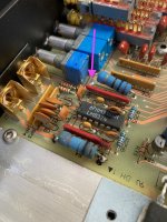
inside and noticed one resistor lifted up and the same one opposite burned on both ends. It's on first two pics:
.
Took it to audio repair expert and after few weeks he fixed it. Replaced the resistors and he got rid of the dust from the inside of the amp.
Back to my man who was doing the install. Couple hours later he called and said that this time it's toasted for real. Before the install I asked him
to check simply with 12v power supply in his workshop. We were able to play the music, green light was on and it switched off without problems.
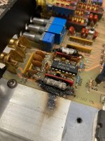
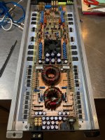
I looked inside again, the smell was really strong and it looked like charred bomb site. 2nd pair of pics:
Took it again to the expert where he said that it looks like I have some issue with the ground wire. He mentioned that before at the first repair
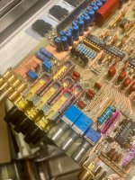
and didn't even see the car......Now 3 months after I went there to see it and again the same resistors are replaced: ( now I know these are 10ohm
shield resistors).
The guy at the repair shop , the expert I mentioned before said the amp turns on, green light is on but removing the remote wire
won't turn it off. It goes in protect mode with the red light. To save time and hopefully my amp as well, I told him I'll ask here on this group.
Now he tries to find out what are these parts for. I marked them with pink color. One is burned black so we cannot identify the values or whatever is
written on it. The second one where the numbers are clear theres no result when I search for it in the web. I've tried
with similar 8pin yellow color ones, just above those brown he removed. I see Korean network resistor but different values.
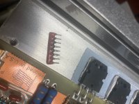
Can you help identify that part? What can cause that amp to stay on after the remote switch off? What he can check or look for in this case? He
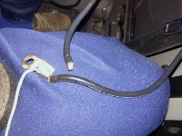
asked me for a schematic but I have only the manuals printed. Also he was right about the ground problem in my car, here's how the ground wire looked
like before I took all the old stuff out and replaced with heavy welding cables
"very good condition and running". First install I had that wrong sound from the speakers, minute after ---
the smell from the trunk so we cut of the power removed it and I took it home. Curious if any damage can be visible, I looked
inside and noticed one resistor lifted up and the same one opposite burned on both ends. It's on first two pics:
.


Took it to audio repair expert and after few weeks he fixed it. Replaced the resistors and he got rid of the dust from the inside of the amp.
Back to my man who was doing the install. Couple hours later he called and said that this time it's toasted for real. Before the install I asked him
to check simply with 12v power supply in his workshop. We were able to play the music, green light was on and it switched off without problems.
I looked inside again, the smell was really strong and it looked like charred bomb site. 2nd pair of pics:


Took it again to the expert where he said that it looks like I have some issue with the ground wire. He mentioned that before at the first repair
and didn't even see the car......Now 3 months after I went there to see it and again the same resistors are replaced: ( now I know these are 10ohm
shield resistors).

The guy at the repair shop , the expert I mentioned before said the amp turns on, green light is on but removing the remote wire
won't turn it off. It goes in protect mode with the red light. To save time and hopefully my amp as well, I told him I'll ask here on this group.
Now he tries to find out what are these parts for. I marked them with pink color. One is burned black so we cannot identify the values or whatever is
written on it. The second one where the numbers are clear theres no result when I search for it in the web. I've tried
with similar 8pin yellow color ones, just above those brown he removed. I see Korean network resistor but different values.

Can you help identify that part? What can cause that amp to stay on after the remote switch off? What he can check or look for in this case? He
asked me for a schematic but I have only the manuals printed. Also he was right about the ground problem in my car, here's how the ground wire looked
like before I took all the old stuff out and replaced with heavy welding cables

What's the resistance between the B+ terminal and either of the non-bridging speaker terminals?
Twist the transformer to see if the resistance changes.
The 10 ohm resistors burned becase the tech didn't use flameproof resistors. Flameproof resistors have a ceramic coating that doesn't flame up. The ones he used had a paint coating that flamed up.
The 8-legged device is a resistor network. The markings give the value. It could be isolated or bussed (see attached).
https://www.mouser.com/datasheet/2/54/4300R-777281.pdf
I will visit him and ask to check that resistance and replace the painted parts to ceramic. I'll try to take a better picture of that 8pin resistor as well.
I type those numbers in many ways and still there's no direct link to the product. Mouser does deliveries here
from their local branch. I went through all the manufacturers logos and I can't find any similar. I have PC2150, PC450,PC4100, PC250
I can look inside and see if they put that resistor in as well, possible?
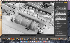


The resistor network is probably OK. Alcohol or acetone will clean up the carbonized material.
The resistors in the amp photos I have for an 1800.2 have the markings 8Y222j. That indicates that it's a 4 resistor, isolated, 2.2k resistor. See attached. You can test it and compare the readings to the other in your photos.
https://one-stop.co.kr/goods/view_contents?no=5520&setMode=pc&zoom=1
To be clear about measuring the resistance between the non-bridging speaker terminals and the B+ terminal, you need to twist while the meter is connected. Clip the meter probes onto those points then twist/push/pull on the power transformer (and the inductor if it's touching the board) while watching the meter.