I've been gradually pulling together the makings of a stereo guitar rig - got a nice rack preamp, stereo effects, stereo 4x12, etc. Still need a power amp though, and as I thought about it I realized that I've got all the parts that I need already on hand - a couple of SE 5K:8 OTs, a PT with enough oomph for something relatively low-power, tubes, a sufficient choke, and even a chassis that will work. I put together this design, and would love to hear any feedback anyone might have.
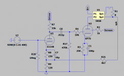
It uses an E1148 (effectively half of a 6SN7) to drive a 6P7S (basically an 807). It sims out to yield 10WPC with 9% THD from a 1VRMS input. Each side idles at about 65mA (21W) on the plate and 4.1mA (1.2W) on the screen. I can't get more headroom out of it because I'm limited on B+, but 20W of "guitar clean" is way more than I can see myself being able to use at home anyway. PT doesn't have a bias tap, so I'm having to do a cap-coupled supply. (Cathode and back biasing, both cost too much Vak.)
The 100K input grid leaks will be individual volume pots. I thought about putting in a presence control, but there's barely any NFB to speak of, so I don't think it would be all that effective.
Anything boneheaded that I'm overlooking here, before I prototype it?
Attachments

Looks good to me!
With the higher transconductance of the E1148 (compared to a half-12AX7), you will need a larger cathode bypass capacitor for the same bass frequency response (-3 dB frequency). But you probably already know that.
-Gnobuddy
With the higher transconductance of the E1148 (compared to a half-12AX7), you will need a larger cathode bypass capacitor for the same bass frequency response (-3 dB frequency). But you probably already know that.
-Gnobuddy
WTH do you need even 10W, much less 20W, "at home"?I'm overlooking here
Self-bias whenever possible!! IMHO, this is possible. 10% less power is still a lease-breaker.
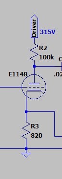
Good points. I gave it a shot and came up with this. Ended up simulating at 9.6WPC and 9.5%THD on 1Vrms input - an utterly negligible difference. Got there by increasing gain in the driver stage, raising the screen voltage to ~310V, and pushing the GNFB to about 6dB. And a bunch simpler.WTH do you need even 10W, much less 20W, "at home"?
Self-bias whenever possible!! IMHO, this is possible. 10% less power is still a lease-breaker.
0.62Vrms input yields 5WPC at 3% THD. So it's (in guitar terms) ultra-clean up to "very loud". Appreciate the tip. I should get around to prototyping it in a few weeks.
Attachments
I'm a bit surprised by your numbers. The E1148 has a μ of 20 so the voltage gain without any feedback would be 15 at best. Part of the resistance in the cathode lead is not bypassed, which creates some negative feedback. The GNFB is 6 dB which halves the gain of the first stage. So I estimate the voltage gain to be something like 6. But is 6 Vrms enough to fully drive the 6P7S? What is the gain of the first stage according to the simulation?
The total resistance in the cathode lead of the E1148 seems very low to me. What is the cathode voltage of the E1148 in the simulation?
The total resistance in the cathode lead of the E1148 seems very low to me. What is the cathode voltage of the E1148 in the simulation?
I'm a bit surprised by your numbers. The E1148 has a μ of 20 so the voltage gain without any feedback would be 15 at best. Part of the resistance in the cathode lead is not bypassed, which creates some negative feedback. The GNFB is 6 dB which halves the gain of the first stage. So I estimate the voltage gain to be something like 6. But is 6 Vrms enough to fully drive the 6P7S? What is the gain of the first stage according to the simulation?
The total resistance in the cathode lead of the E1148 seems very low to me. What is the cathode voltage of the E1148 in the simulation?
Yeah, as a simulation it's dependent on the accuracy of the models, and I'm reusing a model for the 2C22 for the E1148. The 2C22/7193, E1148, CV6, and DET20 are all closely related, but 2C22 is the only one with a decent datasheet and model) . I also made a mistake calculating the NFB, it's actually 3dB, not 6. So with that said ...
Without feedback, input stage gain is 15.8. With feedback, it's 12.2. So 1Vrms in puts ~35Vpp on the 6P7S grid, which is enough to drive it to clipping. The E1148 cathode idles at 1.8V.
In the interest of simplification, I've also been playing with this as an alternative setup. Yields the same gain, but deletes a cap and a resistor, and saves a few ma. The cathode idles right at 2V.
All of this will be mooted by actually prototyping the thing, though. I'll probably put this to bed until I can breadboard it.
Attachments
This is a point that is almost universally misunderstood, by almost every person looking for a tube guitar amp to use at home.WTH do you need even 10W, much less 20W, "at home"?
One single watt into a typical (high efficiency) guitar speaker will produce a sound as loud as multiple trumpets, blown hard, next to your head.
It's not a coincidence that many old myths suggest that a trumpet-blast is loud enough to wake the dead!
Some years ago I found out that ten microwatts of power made a very audible sound through a guitar speaker a metre from my head. I was shocked, until I realized that 10uW is (-50 dBW) of power, but a guitar speaker often has a sensitivity of (+95 dBW). Put together, that means 10uW can produce an SPL of 45 dB. If you Google for sounds with an SPL of 45 dB, you will come up with results like "babbling brook". Quiet, certainly, but quite audible. A babbling brook in your living room might be irritatingly loud after a while.
I like my e-guitar quieter than most guitarists, but for overdriven guitar sounds, I found that 50 mW was already quite loud in the living room. Clean tones can use more power - maybe 200 mW into a guitar speaker.
-Gnobuddy
- Home
- Live Sound
- Instruments and Amps
- Cobbled together SE stereo guitar power amp