Building custom designed amplifiers requires testing the amplifier without damaging it. This is tricky at first, as a newly built amplifier may be out of proper bias by a large margin. For the latter, main power current limiting is essential if not an expensive bench power supply is available. Such a power supply would need to cater for a wide range of voltages and currents and must be capable of supporting shorted outputs. This may seem bad news for potential DIYs but it is not gloomy as it seems, there is a very cost effective way of achieving what a current controlled power supply offers. This humble test is, the famous series light bulb test which uses a filament lamp as opposed to modern bulbs.
Since I built such a protector I am posting it here for any DIY users to illustrate that there is no need of very expensive equipment to make your own testing equipment. Some users have even created an oscilloscope for audio purposes by using a computer's sound card which its own AD converters capable enough for the audio spectrum. In the case of using a computer, it is very important to isolate it to avoid damaging its sensitive circuitry.
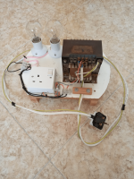
I am posting my series light bulb tester which uses a mains transformer to reduce 230V AC to half its value and pass current through a couple of lights before reaching an amplifier under test. Different bulbs with different ratings can be used.
Since I built such a protector I am posting it here for any DIY users to illustrate that there is no need of very expensive equipment to make your own testing equipment. Some users have even created an oscilloscope for audio purposes by using a computer's sound card which its own AD converters capable enough for the audio spectrum. In the case of using a computer, it is very important to isolate it to avoid damaging its sensitive circuitry.
I am posting my series light bulb tester which uses a mains transformer to reduce 230V AC to half its value and pass current through a couple of lights before reaching an amplifier under test. Different bulbs with different ratings can be used.
Attachments
You're halfway there. Provided your transformer is not an autotransformer you should remove the earth conductor from the socket for the device under test to make it safer to work on, because accidentally contacting a live circuit is much less likely to result in electrocution when the chassis is not grounded.
Then instead of a fixed step-down voltage, a variac with voltage and current metering will allow a soft start to power the device under test to whist monitoring for fault conditions.
Setup becomes: 1:1 isolation transformer ➔ variac (0% to 110%) ➔ bypass-able bulb current limiter ➔ device under test
My bulb current limiter allows switching between different wattage bulbs for low and high current draw circuits, or to start with a small bulb for, say, amplifier initial quiescent setup and then switch to a larger bulb for further adjustment, then bypass altogether for final adjustment and performance tests.
Thanks for your elaboration about this device. An isolation transformer would vastly improve the safety of the equipment and would allow more freedom on the tester. An variable transformer would also be ideal, but the costs do not justify the extra expense.
With CAUTION anyone can use what I posted with success. Even a simple filament lamp in series with the mains can serve the same testing purpose. The purpose of my posts is to stress that it is actually satisfying and economical to built your own amplifier.
To the Administration:
It would make much more sense in the case of the many users who do not afford exorbitantly priced parts to advertise more affordable products.