Hi,
Hope someone can help, I had one channel blown on a sony TA-2650 so replaced the pre drivers and two matching pair of power transistors, powering up with
lamp tester I noticed the bias would shoot up and found SV04F (diode D101 & D201) faulty, If i rapidly cool it with freeze spray the bias shot down again. So got 3x 1N3595 in series mount on the original mounting expoy resigned to the mounting and secured to the original transistor, noticed that the other channel was also fluctuating a bit and very unsteady so replaced that SV04F also, but now the bias only goes to max of about 2mA with the trim pot, the other channel is the same, so the SV04, 3 diodes in series is causing this, as the good channel (fluctuating) on was able to bias higher with old SV04F....does anyone know which resistors I need to up in size or lower in size to compensate please ? Thanks in advance
Attachments
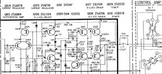
There should be 2.4volts across the diode, not 2.1.
How did you test the diode?
The current feeding the diode is limited to 12mA, so probably not damaged unless the 12mA supply pulling it became very large indeed.
If the diode was faulty, four 1n4148 diodes in series would suffice, the bias is not set by the diode and if it is, there is something very wrong and probably obvious as the bias chain is the preset.
Hi Jon,
Thanks for reply
I tested the diode out of circuit with a multi tester, it tested ok, but Like i mentioned The bias would remain stable at around 20mV across the output resistors
and after a few seconds would go up and could keep it down by blasting compressed air on the diode every few seconds, you are probably correct I will need another one in series, 3 x 1N3595 is probably not enough, as my trim pots are maxed out and only getting about 1.8 to 2mV on the emitters.
Yap that did the trick added a 4th x 1N3595 (400mA) diode, trim pot is a bit sensitive might install multiturn pot, thanks for your help
"bias is not set by the diode and if it is" seems like it would need to adjust the bias with temperature fluctuations on the heat sink, that is the reason it
is there I presume to lower the bias when the heatsink heats up, not sure if expoy resin is ideal to secure them, as I found resin gets soft with heat before. What would the glue be they used on orginals?
is there I presume to lower the bias when the heatsink heats up, not sure if expoy resin is ideal to secure them, as I found resin gets soft with heat before. What would the glue be they used on orginals?
Hi stofbj, can you tell me which transistors you used as replacement (especially the pre drivers)? Thanks!Hi,
Hope someone can help, I had one channel blown on a sony TA-2650 so replaced the pre drivers and two matching pair of power transistors, powering up with
lamp tester I noticed the bias would shoot up and found SV04F (diode D101 & D201) faulty, If i rapidly cool it with freeze spray the bias shot down again. So got 3x 1N3595 in series mount on the original mounting expoy resigned to the mounting and secured to the original transistor, noticed that the other channel was also fluctuating a bit and very unsteady so replaced that SV04F also, but now the bias only goes to max of about 2mA with the trim pot, the other channel is the same, so the SV04, 3 diodes in series is causing this, as the good channel (fluctuating) on was able to bias higher with old SV04F....does anyone know which resistors I need to up in size or lower in size to compensate please ? Thanks in advance
Hi, I used BD139 +BD140 and they seem to be holding up ok so far, they should be easy to get, just make sure you check the data sheet on the pin configuration.
Thank you! I was already planning to use the same BD's 👍 I have -15V dc offset at the right channel and 0V bias.
Hi Guys ...
I have the same amplifier and I buy him with all original parts ... I made a "recap" of all electrolytic capacitors and clean ALPS volume pot.
I tried to set up the bias, using very strict instructions in service manual, Negative measuring probe on ground chassis and positive on emmiter of all power transistors ... I have no problem set -25mV BIAS on Q110 / Q210, but the value on Q109/Q209 is somewhere in the range from -2mV to 10mV ...
I noticed that the amplifier main board has the same measuring contacts as the higher model TA-3650, where only one bias value / per channel is set, but the TA-2650 manual doesn´t mention them ...
In this condition, amplier work´s fine, but I really don´t like a blown up the power trans...
Second "problem" is the noisy output, which is audible from the second third of the volume pot position, which is at least inaudible at minimum or maximum amplification. PS: It´s noise, not a hum or buzz.
Thank´s to all for help !
Martin.

I only used the measuring contacts for setting bias - You mean´s emmiter+GND on all four power transistors or "secret" pins on PCB ? BC550 is small transistors without a hole for screwing onto heatsink, what can I use for fixing him ? Original 2SV04 using something like epoxy glue ...Might be 2SV04. Replaced them with bc550 and 1k + 3.3k resistors. Problems with bias adjustment were solved. I only used the measuring contacts for setting bias.
Thank´s, Martin.
- Home
- Amplifiers
- Solid State
- Sony TA-2650