I noticed on this board that R10 has been changed not sure if it from the factory or someone tried repairing it themselfs .
right now it has a 5.1K resistor .
Does anyone know the correct value ?
Also does anyone know what the purpose of this resistor is ?
also should the pins have a jumper on them set to 9 volts ?
it came out of a 10 k amp
right now it has a 5.1K resistor .
Does anyone know the correct value ?
Also does anyone know what the purpose of this resistor is ?
also should the pins have a jumper on them set to 9 volts ?
it came out of a 10 k amp
Attachments

The resistor value varies greatly between amps.
Do you have photos of other 10k amps that you could refer to?
In some amps, the jumper is for over-voltage protection. Others are for under-voltage. Are any of the 3-pin header pins connected to ground?
Do you have photos of other 10k amps that you could refer to?
In some amps, the jumper is for over-voltage protection. Others are for under-voltage. Are any of the 3-pin header pins connected to ground?
Non of the pins on the header connect directly to ground .
Also on the schematic R10 says 6K8 . So not sure if that’s what is suppose to be in the location or it was replaced by someone else .
Also on the schematic R10 says 6K8 . So not sure if that’s what is suppose to be in the location or it was replaced by someone else .
Does any pin of the header connect directly to pin 11 of the 494?
If you post the diagram, it would remove some of the guesswork.
If you post the diagram, it would remove some of the guesswork.
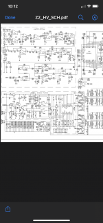
That diagram doesn't have the 3-pin header.
It's a typical 11-pin PS driver board. Other similar boards have R10 as high as 18k.
R10 works with the thermistors as well as the threshold voltage for the thermal comparator to tell the amp what the shutdown point will be.
Do you have a photo of other driver boards with the 3-pin header?
It's a typical 11-pin PS driver board. Other similar boards have R10 as high as 18k.
R10 works with the thermistors as well as the threshold voltage for the thermal comparator to tell the amp what the shutdown point will be.
Do you have a photo of other driver boards with the 3-pin header?
Yes I have photos of other driver boards with the 3 pin header . Do you want me to post them ?
Also I’m not sure if this driver board is original to this amp or not sonce I bought the amp blown from someone and it was an attempted fix using parts from other amps
Also I’m not sure if this driver board is original to this amp or not sonce I bought the amp blown from someone and it was an attempted fix using parts from other amps
What is R10 on the other photos?
Also compare the resistors near the 393.
What is the make/model of the amp?
Also compare the resistors near the 393.
What is the make/model of the amp?
It’s a Digital Designs Z2HV .
Other driver boards I have here have a 15k ,or a 13k resistor in R10.
i have a pic of the Z2LV of this amp and the 3 pin header has the jumper on it set between 9v and the middle pin but I can’t make out the value or R10 since the photo is blurry
Would it be ok to run this amp once I finish rebuilding it with the resistor that’s in R10’s location ?
The Z2 has a driver board without the jumper from the information I have. Do you have a standard 11 pin PS driver board that you could use?
How many thermistors do you have in this amp?
How many thermistors do you have in this amp?
Next question this amp uses FMG36S and FMG36R for the rectifiers.
Is there a good replacement for these ? Some of them have broken legs and a couple the legs are broken at the body so can’t solder to them
Is there a good replacement for these ? Some of them have broken legs and a couple the legs are broken at the body so can’t solder to them
APT30D60BCTG is positive. Download the datasheets. The rectifier with the diodes pointing in is the positive rectifier.
- Home
- General Interest
- Car Audio
- Driver board Question