Hi all, I've found and bought two original board of Futterman OTL3 but I can't find any information about the secondary voltage and power of psu trafo of this amp. I can built a new trafo but I need some help about these value. The only information I've is about the filaments of 6LF6, each tube is about 2,5A. Many thanks in advance
Best bet is to contact George Kaye and ask his advice as they are his design and he still mod's and services them.
gakjazz@gmail.com 1-802-257-5085
Tell him matthew victor gave you the contact info.
I hope to read you've got them singing again!
gakjazz@gmail.com 1-802-257-5085
Tell him matthew victor gave you the contact info.
I hope to read you've got them singing again!
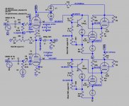
Beside the 2 heaters winding voltage (depending of XLF6 you already know, there are 3 other windings :
1. lower grid filter cap 100v, or AC 70V, not so critical as the bias if adjustable
2. upper screen, filer cap ?v, stack on top 360v cap of power tube rail (will verify with SIM), also supply the front with 400V cap C5 (via 220k), can you read C12 value?
3. Single power tube rail, filer cap 360v (Tot 9000u). The actual voltage (say 10% safety margin) is about 320V, say 300V or 150V each back bank. Pdissp max. is 40W*6=240W. So the AC voltage of the winding is 300/1.42=~220V AC about 300VA. After rectified you give more or less 300V DC.
Attachments
I think that filer cap C12 is 600uf 360V, if so, given the safe margin, this winding will be 220V AC, after rectified give 300V stack on top of power tube rail, a total of 600V. What do you think? Now I can sim base on this.2. upper screen, filer cap ?v
Thx so much, really!Best bet is to contact George Kaye and ask his advice as they are his design and he still mod's and services them.
gakjazz@gmail.com 1-802-257-5085
Tell him matthew victor gave you the contact info.
I hope to read you've got them singing again!
THX , very interesting!Beside the 2 heaters winding voltage (depending of XLF6 you already know, there are 3 other windings :
1. lower grid filter cap 100v, or AC 70V, not so critical as the bias if adjustable
2. upper screen, filer cap ?v, stack on top 360v cap of power tube rail (will verify with SIM), also supply the front with 400V cap C5 (via 220k), can you read C12 value?
3. Single power tube rail, filer cap 360v (Tot 9000u). The actual voltage (say 10% safety margin) is about 320V, say 300V or 150V each back bank. Pdissp max. is 40W*6=240W. So the AC voltage of the winding is 300/1.42=~220V AC about 300VA. After rectified you give more or less 300V DC.

Added display for upper and lower screen supply current. 600*20mA+300*20mA=12+6=18W + front end stage. Upper screen supply winding =6W+ frontend or >10VA .
Attachments
Last edited:
Many Thx for your useful scheme!Added display for upper and lower screen supply current. 600*20mA+300*20mA=12+6=18W + front end stage. Upper screen supply winding =6W+ frontend or >10VA .
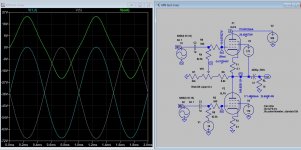
There is a problem with simulation using the transistor TIP50 and zeners diode 80v and 70v so I used PNP TIP41C. Now I get it to work with TIP50 (NPN) but the zener is 36V and 56V. Anyway, the idea is get the supply voltage to output 1/2 HT or 150V to bias the screen, is adjustable but not more than 170V max allowed.Admittedly I just don't get what these PNP's and 80Vdc voltage sources are for...
Attachments

As a tube powered voltage regulator basically doesn't need more than the pass tube, the amplifier tube, the voltage reference and an output voltage divider, I assume these transistors' purpose is to increase the regulators' loop gain?
Best regards!
Best regards!
The transistor I think is working as a current sink for voltage divider, it may work by directly feeding the grid of regulator without the transistor. Now seem tieing the two have some difficulties or problem I am not sure with modern components. The gear is sbout 40 years old.
- Home
- Amplifiers
- Tubes / Valves
- Futterman OTL3 power supply trafo