Somebody could do me a favor…
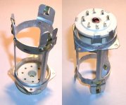
I am working on a new build, GU-50 PP and in the PCB design phase. I did order tubes and sockets and got a serious question about the GU-50 sockets I decided to use.
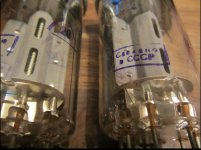
If somebody has these sockets, see attached picture, lying around at home, or knows somebody who has, I need some info.
Please post a Straight picture bottom view, onto the pins with the mounting flange on the cage visible. I am trying to get the distance of the mounting holes on the flange on the cage and most importantly the angle of this virtual square —4 holes on the flange— towards pin 1. I have the suspicion that pin 1 is not at 90° (or 45°) to the holes on the mounting flange. It looks like 5°-10° off. I do have the pin layout information, angles, diameter of the circle they are aligned at. Don’t need that. Need info about this specific cage and mounting flange on the cage only.
From that perspective view picture it is impossible to gather any useful information in regards to dimensions.
I am working on a new build, GU-50 PP and in the PCB design phase. I did order tubes and sockets and got a serious question about the GU-50 sockets I decided to use.
If somebody has these sockets, see attached picture, lying around at home, or knows somebody who has, I need some info.
Please post a Straight picture bottom view, onto the pins with the mounting flange on the cage visible. I am trying to get the distance of the mounting holes on the flange on the cage and most importantly the angle of this virtual square —4 holes on the flange— towards pin 1. I have the suspicion that pin 1 is not at 90° (or 45°) to the holes on the mounting flange. It looks like 5°-10° off. I do have the pin layout information, angles, diameter of the circle they are aligned at. Don’t need that. Need info about this specific cage and mounting flange on the cage only.
From that perspective view picture it is impossible to gather any useful information in regards to dimensions.
Attachments
Last edited:
Thank you.
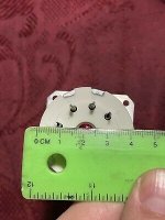
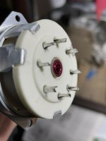
I have this picture. I need a picture of the cage with the mounting flange! Please see my OP and see the attached picture. There are 4 holes on the cage/mounting flange…
This is what I am getting, see attached. An info like this is Not good enough for a PCB design.
It’s better to just have a straight picture showing all pins and all 4 mounting holes on the flange /cage.
I have a known distance, 25mm circle of the pins which I can correlate then to the other dimensions. On the pictures attached you don’t see all pins and you don’t see all 4 mounting holes…
It’s better to just have a straight picture showing all pins and all 4 mounting holes on the flange /cage.
I have a known distance, 25mm circle of the pins which I can correlate then to the other dimensions. On the pictures attached you don’t see all pins and you don’t see all 4 mounting holes…
Attachments

Since that socket isn't strictly a PCB socket, it has solder cups. Another alternative would be to just route a big hole in the PCB, with four mounting holes for the saddle. Then mount the socket on standoffs of the board backside, pins up, then jumper wire the solder cups into the circuit topside. the grid stopper can also be close on the pin too this way. Also good for heat as hot pins would not be conducting heat into traces and the big hole allows convection around the whole socket.
My sockets are a bit different, see attached…Thank you all! Great community!
I’ll share my project…
So, dimension is 35mm.
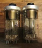
The GU-50 I order do not have the middle tube.
Attachments


Just a hopeful question.
Does anyone know the thread size of the red coloured screws and nuts in this picture. I imagine they must be metric.
- Home
- Amplifiers
- Tubes / Valves
- GU-50 Sockets