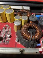
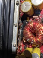
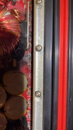
Hey all, need help rebuilding the power supply end of my Kicker 06ZX750.1 (commonly known as the Redline version) got it from a buddy, looks like a wire fell down into the amp, causing a blowout on a power supply mosfets (can see the wire strand melted onto the leg of the mosfet that initially blew, taking out all the others) output side tested good diode test wise, so it’s looking like just the mosfets and gate resistors need to be replaced, there’s also one bulging cap in going to replace as well. I have an Oscope, soldering irons with diff solders and fluxes, a 12v90amp PS (non adjustable) but also a battery/charger setup for the low stuff, waiting on hot air gun and an adjustable 12-20v 0-10amp tech power supply. Replacing PS side mosfets with what a buddy recommended, Infineon IRF3205PBF-ND (((N-Channel 55 V 110A (Tc) 200W (Tc) Through Hole TO-220AB))) trying to figure out the SMD gate resistors, he said they should be 100 (10ohm) but doesn’t know exact specs, hoping to find some help or someone who’s done the power supply repair on this amp. This is my first amp repair, I’ve done some reading but need to do ALOT more, I’m pretty capable, I build high end gaming watercooled PCs, rebuild subwoofers, certified electrician apprentice, few degrees in networking and hardware, I also model/mod WH 40k ...I’m a decent nerd and good with my hands, lol 🤓 so ya, any help would be GREATLY appreciated, thx all 🙂 I’m off to read on previous threads of similar models and similar meltdowns, read read read lol. Added a bunch of photos I was sharing with my new buddy, who does rebuild amps. I thought the gate resistors were like the others, 104, but he said they are 100 (which means 10ohm he said?) so ya, enjoy and thx in advance 🙂
Attachments
-
 6C56257A-8692-43DE-899D-1B484B1B7F72.jpeg517.1 KB · Views: 121
 -
 A36658A9-E312-4694-AC13-A064809234DB.jpeg515.8 KB · Views: 122
 -
 BB39730A-DF2D-4210-9AF7-95DABD84837C.jpeg437.4 KB · Views: 112
 -
 7DFD01F0-CEED-41A5-BC86-0D4B2A16AA89.jpeg646.8 KB · Views: 141
 -
 B63F3200-D8B7-45A0-9D0B-37353064ED20.jpeg324.3 KB · Views: 122
 -
 6D611478-A5D9-4439-90B0-1AA5AC08709A.jpeg437.5 KB · Views: 126
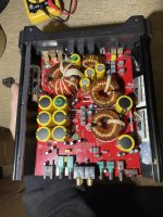
I’ll be breaking down board/removing from case in just a few hours, will have better pics then if needed
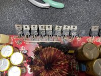
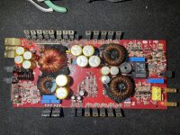
More pics, board removed from heat sink, going to remove the bad mosfets and gate resistors and clean up all the burn in the meantime, also seeing 101 on the gate resistors.
Attachments
Last edited:
I just measured all the gate resistors and they are all measuring exactly 100ohm, meaning they are good right? Or am I wrong?
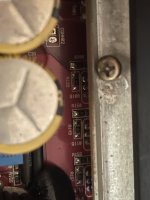
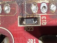
Output Side readings: All the 104 give a reading of 50k except the one next to the resistor im pointing at, that 104 gives a full reading of 100k, which is what’s it’s rated at but I’m assuming the others are reading 50k cuz they wired (parallel/series?) with the 100, which reads 10ohm usually except the one I’m point at, gives no reading/is dead. Which is why the 104 next to the one I’m pouting at is reading full 100k/different then all the others? Logic sound?
Attachments

Last edited:
The resistor I’m pointing at is actually reading 150kohm instead of the 10ohm it’s supossed to read, assuming it’s bad? Why do all the others on this side read 50k instead of 100k? They pop 100k for just a second then go down to 50k. Should each read its value regardless of anything?
The resistor you are pointing at should be a 100K ohm value. There is one across the Gate-Drain leads of all output mosfets. You should read 33k ohm the outside leads of the IRF9640 banks and 50k ohm across the IRF640 banks,
Ty Bill 🙂
Edit:
R210 it’s reading 150k ohm, it should read 10 ohm tho correct? Just to make sure I’m going to replace all 3 9640 mosfet gate resistors marked 100.
Edit:
R210 it’s reading 150k ohm, it should read 10 ohm tho correct? Just to make sure I’m going to replace all 3 9640 mosfet gate resistors marked 100.
Last edited:
R209 is reading 100k (spec value but supossed to read 33k correct?) R210 is reading 150k ohm (spec value is 10 ohm) but this bad value is effecting adjacent values as well? just to be clear 🙂
The spec value of the resistors are 10 ohm and 10k ohm. The 10 ohm gate resistors will read 10 ohm in circuit. The 100k ohm resistors are in parallel within each bank. The 9640 bank have three in parallel reading 33k ohm in circuit and the 640 bank two in parallel read 50k ohm.
That is exactly what one side reads, this one resistor on other side threw me for a loop, and I just randomly started testing resistors after finding a calc to determine value, glad I did lol 🙂
The markings can be confusing. It depends on the manufacturer. You will typical see 100 for 10 ohm.101 for 100 ohm, 102 for 1000 ohm etc The third digit is a multiplier
- Home
- Amplifiers
- Power Supplies
- Kicker 06ZX750.1 power supply meltdown ...