Hi,
So the fan of my amp started to smoke after I turned it on . I turned it off immediatlyj , then try again to turn it on, smoke again , so I turned it off again.
I repeat it couple of time until I thought " yeah , that fan must be well-cooked now , I'm good for getting a new one".
Changing the fan is not a big deal for me , but my worries goes about the cause of all of this. the fan is a 12 V , so I mesured the voltage on the outlet of the board ( where the fan's wire are plugged) and i mesured 81 V DC .
So my question is , is that normal ?
I don't want to burn a new fan again , so I would be very grateful if someone could help.

Use a mains powered fan in parallel with the primary side of the supply.
Those DC fans are squirrel cage solid rotor motors, there is a circuit inside to convert DC to AC.
And those are less reliable than mains powered fans, which have the same construction.
Also, fix the high voltage problem, whatever caused it could have caused other damage elsewhere in the circuit.
Those DC fans are squirrel cage solid rotor motors, there is a circuit inside to convert DC to AC.
And those are less reliable than mains powered fans, which have the same construction.
Also, fix the high voltage problem, whatever caused it could have caused other damage elsewhere in the circuit.
Thanks PFL
I suspect two problems.
1) the Fan regulator circuit is blown (series pass transistor?)
You must have +48V at fan terminals only with a very hot amp, or much lower when cold.
2) A former amp owner may have replaced proper 48V fan with a plain vanilla 12V one, and got away with it because there is a "minimum speed setting" which might be near 12V ... and it would hold, sort of, at home levels.
But the moment your amp warmed up significantly, it nuked the fan and resuting short killed driver transistor.
Replace both with proper parts.
A clarification, the mains powered fans are squirrel cage motors, the windings may have impedance protection, but they do not have any DC / AC circuits.
Sleeve and ball bearing versions are available from many reputed makers.
Sleeve and ball bearing versions are available from many reputed makers.
that's right , mine is another series , it's the "AH 300-7", with a seven band graphic EQ , and I believe the schematic should be this one :In this Service Manual for the "AH300 Series 6" the fan voltage is given as 48 Vdc, but maybe your amplifier is from an other series.
Attachments
Thanks JMFahey,Thanks PFL
I suspect two problems.
1) the Fan regulator circuit is blown (series pass transistor?)
You must have +48V at fan terminals only with a very hot amp, or much lower when cold.
2) A former amp owner may have replaced proper 48V fan with a plain vanilla 12V one, and got away with it because there is a "minimum speed setting" which might be near 12V ... and it would hold, sort of, at home levels.
But the moment your amp warmed up significantly, it nuked the fan and resuting short killed driver transistor.
Replace both with proper parts.
I updated the schematic , but i'm not sure to understand of what should the fan's spec.
Still, I have 81Vdc on the fan's outlet with a cold amp .The fan regulator circuit must be clearly malfunction , do you think you can help me locate it exactly on the scheme ?
Maybe.
Point is TE like any other Factories modifies schematics along the time.
FWIW the "7" in the name refers more to amount of Graphic EQ bands (7 or 12) than anything else, a "7" is not "the next model after 6", they may very well be contemporary.
My point is that I am slightly worried at the +81V measured , which are "way too much" for the GP300-7 shown,where I expect around 70V rails, indirectly confirmed by 80V main filter caps.
On the other side, on the higher voltage one, I would expect a 48V fan.
So just in case I suggest you check whether the simpler TIP31C based circuit kindly supplied by turk182 applies, or the more complex one shown in the first schematic:

No need to detect all the components to find which one applies, just 2 or 3 checkpoints are enough:
1) (the least reliable because it might not be original): BD679 or TIP31C?
2) a 16V Zener (post code if not sure, you´ll need a jeweller´s loupe for that he he, at least I do) or a 51V one, in parallel with an (presumably) 25V or so 10uF electrolytic or a 63V or higher one
3) ONE Zener present vs. TWO
4) a "minimum speed" trimmer vs none.
5) ONE mid sized transistor (TO220 or similar) or one plus a small (TO92) one.
Not all needed to decide, I suggest them "just in case".
6) a picture closeup showing that area might help.
Again, I am slightly worried by the +81V present hinting at the high voltage version.
What voltage are main power supply caps?
That said, the simpler TIP31C version can work from a +81V rail.
Point is TE like any other Factories modifies schematics along the time.
FWIW the "7" in the name refers more to amount of Graphic EQ bands (7 or 12) than anything else, a "7" is not "the next model after 6", they may very well be contemporary.
My point is that I am slightly worried at the +81V measured , which are "way too much" for the GP300-7 shown,where I expect around 70V rails, indirectly confirmed by 80V main filter caps.
On the other side, on the higher voltage one, I would expect a 48V fan.
So just in case I suggest you check whether the simpler TIP31C based circuit kindly supplied by turk182 applies, or the more complex one shown in the first schematic:
No need to detect all the components to find which one applies, just 2 or 3 checkpoints are enough:
1) (the least reliable because it might not be original): BD679 or TIP31C?
2) a 16V Zener (post code if not sure, you´ll need a jeweller´s loupe for that he he, at least I do) or a 51V one, in parallel with an (presumably) 25V or so 10uF electrolytic or a 63V or higher one
3) ONE Zener present vs. TWO
4) a "minimum speed" trimmer vs none.
5) ONE mid sized transistor (TO220 or similar) or one plus a small (TO92) one.
Not all needed to decide, I suggest them "just in case".
6) a picture closeup showing that area might help.
Again, I am slightly worried by the +81V present hinting at the high voltage version.
What voltage are main power supply caps?
That said, the simpler TIP31C version can work from a +81V rail.
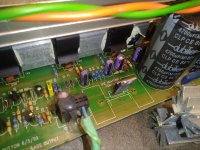
In fact , there was an exact issue about TR7 : When I opened the amp, I discovered that the heatsink attached to TR7 had its legs broken from the board, and that heatsink was just moving away freely in the box. but the TR7 seems to be in a good shape , no burn or explosed.View attachment 1006352 (page 3) this is the fan circuit so TR7 or the zener must have failed. C16 did not explode??
As that amp was making no sound after one hour of play, I concluded that was because of the heat accumulated due to fan and heatsink failure.
Fixing the heatsink is gonna be fine , but that 81 V on the fan scared me .
C16 did not exploded , althought its top look a bit rounded, like pushed a bit from the inside.
So TR7 is a TIP31C, and it's getting 81 V.
And also the main power supply caps are giving 81 V.
Actually , I don't know how to procede how to test if the Zener are fine. Would you mind explain me how to detect a default Zener ?
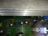
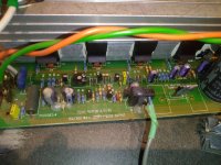
here some pics of the beast :
And also the main power supply caps are giving 81 V.
Actually , I don't know how to procede how to test if the Zener are fine. Would you mind explain me how to detect a default Zener ?
here some pics of the beast :
Attachments
Zener's conduct in a similar way to an ordinary silicon diode when forward biased however, when reverse biased they conduct when the applied voltage across the Zener reaches the marked value. When that point is reached the Zener conducts heavily. Low voltage Zener's can appear 'leaky' compared to ordinary diodes.Actually , I don't know how to procede how to test if the Zener are fine. Would you mind explain me how to detect a default Zener ?
If the circuit is similar to the one in post #10 by JMFahey then the circuit is in two parts. The transistor, R31 which is 10k and the 51 volt Zener form a simple series pass regulator. In that circuit you should never see more than 51 volts on the Zener and slightly less than that on the emitter of the transistor.
You may see less than 51 volts because TR6 can pull the voltage lower on the Zener and so reduce the fan speed.
So if you see more than 51 volts on the fan then there is a problem with either or both the 51v Zener and pass transistor.
The 6v2 Zener sets a voltage limit at that point in the circuit. You may see up to 6.2 volts on the Zener but also less is still valid.
Take away points for that circuit...
If the Zener's are leaky then you will really only prove that by substitution unless you are more experience and can arrange to pass a couple of milliamps through them in a test set up and measure the voltage across them.
If the Zener has a voltage across it close to the marked value then chances are it is good. In this circuit seeing less is valid.
If you see more than the marked voltage across any Zener in a DC circuit (like this) then it is faulty.
C16 will need replacement its bulging.
transistors can fail and dont always show burns or obvious visual failure.
broken heatsink might be easy fix, but could be red flag pointing to your problem
as mentioned its likely the zener or the transistor and both can be tested with multimeter.
lots of tutorials online.
simple resistance test can usually find bad zener , resistance will be high in one direction, lower the other if good.
if resistance is high or low in both directions it can tell you if its failed open or closed. basically just bad either way
its not good to guess, but test. but my guess is the transistor is seeing the most heat and current all its life.
so likely failed, then killed c16 and your fan
http://www.learningaboutelectronics.com/Articles/How-to-test-a-zener-diode
http://www.learningaboutelectronics.com/Articles/How-to-test-a-transistor
Last edited:
another possibility is for whatever reason the heatsink mounting posts broke.
maybe dropped amplifier, or just broke over time from transport vibration.
only thing holding it there was transistor legs and solder connections.
over additional time all the weight and movement stressed the transistor solder
connections to break/ crack or be intermittent. or pushed through and shorted to case.
either way, fun part is the whole board needs to be flipped over so you can solder new components in.
so its a fun process of what needs to done to flip it over.
sorry that was a brainfart question about the multimeter....Mooly he is dealing with the fan circuit i supplied, the board designation is clearly Z3, in the other model it's Z5 and although it's been awhile since i've done a repair on either as i recall this was a lynch pin problem from as far back as the early days of the output boards being silkscreened with "The Bipolar Bear".
great bass amps when they're running well but i just sent 3 chassis that i held for parts to scrap...

the other type has two zener's.
great bass amps when they're running well but i just sent 3 chassis that i held for parts to scrap...
the other type has two zener's.
was there a mica insulator and if so what's it's condition?
according to spec's the Tip 31 c should survive the zener going "open" which would be why we're seeing 81 vdc at the fan terminals.
according to spec's the Tip 31 c should survive the zener going "open" which would be why we're seeing 81 vdc at the fan terminals.
easier to test to be sure.
good news is, very simple circuit, not much to go wrong.
only expensive if something does go wrong.
I think design is genius, no need for fan controller or fault indicator.
anything go wrong , fan starts smoking
just like ancient Indian smoke signal. 😉
good news is, very simple circuit, not much to go wrong.
only expensive if something does go wrong.
I think design is genius, no need for fan controller or fault indicator.
anything go wrong , fan starts smoking
just like ancient Indian smoke signal. 😉
Weird, heatsinks are bolted or tightly clamped to transistors they are cooling, any signs of that?When I opened the amp, I discovered that the heatsink attached to TR7 had its legs broken from the board, and that heatsink was just moving away freely in the box.
Visual clues mean little to nothing in Electronics.TR7 seems to be in a good shape , no burn or explosed.
Measure voltage at: Emitter - Base - Collector and post results.
What does that mean?As that amp was making no sound after one hour of play,
Amp was playing normally and the suddenly it cut off?
Were you playing at band level (hint: hot) or bedroom level? (hint: cold)
Maybe, but please state playing level.I concluded that was because of the heat accumulated due to fan and heatsink failure.
Also us, but that voltage appears also across C16,what do you measure there?Fixing the heatsink is gonna be fine , but that 81 V on the fan scared me .
Visual looks mean little to nothing, measure voltage across it.C16 did not exploded , althought its top look a bit rounded, like pushed a bit from the inside.
No need to remove board or unsolder it, Z3 is in parallel with it.
That said, a heavily bulged top is a bad sign, but let´s add some numbers to that (actual voltage present).
Zeners "zene" 🙂 meaning they guarantee and keep a certain voltage drop across them, and you can measure that.I don't know how to procede how to test if the Zener are fine.
Meaning: I expect rated voltage across a Zener., so, for a 16V zener:
* 16V : GOOD
* 0 or 0.7V : BAD (shorted)
OR: it is not getting voltage from supply. (it is not being turned ON)
* >> than 16V , anything above, say, 17V , including +81V :OPEN
So please, measure and report.
No need for YT tutorials, just measure it in circuit.
I´m not a fan of pulling parts just to be measured outside, unless you can´t avoid it.
It has a job to do, it either does it or not, you can measure that.
That.my guess is the transistor is seeing the most heat and current all its life.
so likely failed, then killed c16 and your fan.
I´d add that I guess C16 died long ago, but TH1 limited current into 12V fan ... until heatsinks warmed up and that little fan motor revved up more than a dentist´s drill.
An antipersonnel mine waiting to be stepped on.
Mica insulators not strictly needed on an apparently "floating" heat sink.
In any case, some kind of clamp must have held transistor tightly against heatsing.
As of parts having legs broken in transport and flying around, after 51 years of bands on tour duty I have seen my share of horror stories.
From power transformers hanging from wiring only and acting as wrecking balls to tiny "harmless" nuts or washers shorting high power rails.
Again, please measure voltage across Zener and at each TIP31 leg.
And hace a C16 replacement on hand ... besides a new 12V fan.
Also show any labels on the fan.
- Home
- Live Sound
- Instruments and Amps
- Bass amp with a burnt fan - voltage - Trace elliot AH 300