Hi All
Direct coupled tube amplifier 11HM7 and GM70,11HM7 (12GN7a) triode connected,anode direct connected to GM70 grid. I can connect the load aluminium housed resistor 12K or caddock mp930 5K+5K+2K on three separate heat sink to anode 11HM7 and grid GM70.
View attachment ATE Resistors2.pdf
View attachment MP9000_Series.pdf
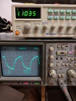
I tested both loads with square wave separately on the table from the generator through a 12k carbon resistor and in the amplifier. The oscilloscope memorizes the impulse of the first load in memory, then I switch the load with the toggle switch and observe the impulse of the second load. With the recall button I select the impulse of the first load and watch both impulses at the same time. The pulses on the anode 11HM7 -grid GM70 are the same at all frequencies 10Khz,100Khz,1Mhz.Full pulse coincidence on the oscilloscope screen.Parameters are the same. Please advise which is better resistor for sound.
 [/ATTACH]


Direct coupled tube amplifier 11HM7 and GM70,11HM7 (12GN7a) triode connected,anode direct connected to GM70 grid. I can connect the load aluminium housed resistor 12K or caddock mp930 5K+5K+2K on three separate heat sink to anode 11HM7 and grid GM70.
View attachment ATE Resistors2.pdf
View attachment MP9000_Series.pdf
I tested both loads with square wave separately on the table from the generator through a 12k carbon resistor and in the amplifier. The oscilloscope memorizes the impulse of the first load in memory, then I switch the load with the toggle switch and observe the impulse of the second load. With the recall button I select the impulse of the first load and watch both impulses at the same time. The pulses on the anode 11HM7 -grid GM70 are the same at all frequencies 10Khz,100Khz,1Mhz.Full pulse coincidence on the oscilloscope screen.Parameters are the same. Please advise which is better resistor for sound.
[/ATTACH]Attachments
Last edited:
From what I can see one is wirewound (not clear if non-inductively or not), and
the other is some proprietry ?metal?-film type called Micronox (with no transparency at all on voltage coefficient or excess noise, although if its definitely metal film its absolutely fine).
Go with the cheapest if they test identical in your rig I'd say..
Audio is not demanding of resistors so long as you avoid carbon really...
Thanks, the ATE resistor is cheaper, it needs one heatsink, but it is interesting to know the experience of listening and influence on the sound. One of them should definitely sound better.
...One of them should definitely sound better.
In what circuit? For what sounds?
You can't reduce this to a one dimensional answer.
Get and try both/all in your system.
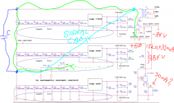
This is a circuit,simplified.

I wanted to finish the design first, at this time I have disassembled speakers-JBL 123A 600L box + tweeter. This is a difficult (for me) amplifier, stab on transistors + -300v, 750v, + - 15v, 6.3v, 5.5v, 20v,there is a circuit for tracking and automatic current adjustment GM70,5 tube rectifier, several transformers and chokes, no case, half of the parts are still on the table, I wind all the transformers and chokes myself, it's a lot of work.so it's hard for me to start listening.
I wanted to finish the design first, at this time I have disassembled speakers-JBL 123A 600L box + tweeter. This is a difficult (for me) amplifier, stab on transistors + -300v, 750v, + - 15v, 6.3v, 5.5v, 20v,there is a circuit for tracking and automatic current adjustment GM70,5 tube rectifier, several transformers and chokes, no case, half of the parts are still on the table, I wind all the transformers and chokes myself, it's a lot of work.so it's hard for me to start listening.
Last edited:
Your schematic is kinda confusing in regards to the supplies. You have a negative 300V in series with a positive 290V, giving -10V on the input tube's plate...?
Both those resitors are probably fine, but different technology. The Caddocs do not handle pulses well, but in your placement that should not be an issue. The are 'non inductive' but for that to have any meaning at all you must lay out your build for the smallest possible loops or else you have inductance right there completely swamping out the benefits of those resistors.
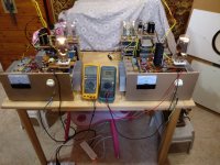
Your rectifiers look to be a foot away from the capacitors, and your wiring is a compllete mess with massive loops all over the place.
Before taking nit-picking measurements I'd tidy up the layout first so that your parts start to have the least amount of external capacitive and inductive parasitics.
Other wise I like the circuit. I am building a similar topology myself at the moment.
Both those resitors are probably fine, but different technology. The Caddocs do not handle pulses well, but in your placement that should not be an issue. The are 'non inductive' but for that to have any meaning at all you must lay out your build for the smallest possible loops or else you have inductance right there completely swamping out the benefits of those resistors.
Your rectifiers look to be a foot away from the capacitors, and your wiring is a compllete mess with massive loops all over the place.
Before taking nit-picking measurements I'd tidy up the layout first so that your parts start to have the least amount of external capacitive and inductive parasitics.
Other wise I like the circuit. I am building a similar topology myself at the moment.
I redrawn the schematic more clearly and added photos of the design.

Yes, the rectifiers are far away, but this is not essential, everything else is in one place.The stabilizers boards are located just above the capacitors pins,very close, 1cm.
Photo of capacitors without a heatsink and PCB stabilizers.

Photos of the left and right sides of the amplifier.
There are black electrolytic capacitors under the heatsink.


I read in the forums that some people don't like caddock, and I found a MIL-PRF-18546 G specifications for my wire resistor, it's not produced for AC voltage.
And what scheme do you design?
Yes, the rectifiers are far away, but this is not essential, everything else is in one place.The stabilizers boards are located just above the capacitors pins,very close, 1cm.
Photo of capacitors without a heatsink and PCB stabilizers.
Photos of the left and right sides of the amplifier.
There are black electrolytic capacitors under the heatsink.
I read in the forums that some people don't like caddock, and I found a MIL-PRF-18546 G specifications for my wire resistor, it's not produced for AC voltage.
And what scheme do you design?
Kinda like this then. It seems your signal path for the output is thru both one of the 300V and the 740V supply in series. You might want a common cap for the signal loop? (Drawn in blu and teal...)
I find it confusing when you write -300-340V and -765-830V which I guess is the 0V reference for the positive voltages, and not that you have +-V supplies...?
Your main power loop, with the high currents thru the OP-stage, is going thru two series voltage supplies. Why not make one single 1040V supply and bleed off the lower voltage for the driver from that?
My amp is lower wattage and based on low mu tubes. I'd love to try the GM70 some day.This topology isn't great for higher mu tubes I think. But with split supplies I guess higher mu tubes work fine. High mu tubes require active loads on the driver since the voltage swing is so small the load resistor will be too small. But with active CCS load I guess higher mu tubes are fine. I just want it as simple as possible and with low mu tubes I can have 'proper' plate resistance on the driver tube.
Attachments
I like your Cu-foil and cap units. Very nice, I do similar solutions. It's not easy making small loops at high voltage. The parts are naturally large and we need space for everything. Keeping it tidy and minimizing loops is easier said than done.
You drew everything correctly, but it is not necessarily to put one common capacitor, one common capacitor consists of two series-connected capacitors at the output of the stabilizers 300V and 740V.
A separate rectifier is connected to the voltage -300-340V and +300 + 340V, and a separate rectifier is connected to the voltage -765-830V and +765 + 830V.
I round-off the voltage value to make it easier to calculate, so they don't quite match.
Voltage values at the output of the first and second stabilizers 300V are adjusted from 280V to 300V to obtain current GM70 95-98ma.
You can make a single stabilizer for 1040V, but then the load will additionally dissipate a power of the load 12GN7A: 32mA x 740V = 23.7W.
This is a good technical design,but I do not use CCS and transistors in the path of the signal –for me the most linear load is the resistor.
A separate rectifier is connected to the voltage -300-340V and +300 + 340V, and a separate rectifier is connected to the voltage -765-830V and +765 + 830V.
I round-off the voltage value to make it easier to calculate, so they don't quite match.
Voltage values at the output of the first and second stabilizers 300V are adjusted from 280V to 300V to obtain current GM70 95-98ma.
You can make a single stabilizer for 1040V, but then the load will additionally dissipate a power of the load 12GN7A: 32mA x 740V = 23.7W.
But with active CCS load I guess higher mu tubes are fine. I just want it as simple as possible and with low mu tubes I can have 'proper' plate resistance on the driver tube.
This is a good technical design,but I do not use CCS and transistors in the path of the signal –for me the most linear load is the resistor.
Last edited:
This is similar to your schematic.
View attachment Lynx LW.pdf
cross reference for tube УО186 it is AD1 tube.
GM70 amplifier with Fiat transformers
dc coupled gm70 amplifier
View attachment Lynx LW.pdf
cross reference for tube УО186 it is AD1 tube.
GM70 amplifier with Fiat transformers
dc coupled gm70 amplifier
Last edited:
as I know, the Caddock MP 9000 series is a film resistor (Micronox® resistance film fired onto a flat ceramic substrate) - go toHi All
Direct coupled tube amplifier 11HM7 and GM70,11HM7 (12GN7a) triode connected,anode direct connected to GM70 grid. I can connect the load aluminium housed resistor 12K or caddock mp930 5K+5K+2K on three separate heat sink to anode 11HM7 and grid GM70.
View attachment 1002560
View attachment 1002561
I tested both loads with square wave separately on the table from the generator through a 12k carbon resistor and in the amplifier. The oscilloscope memorizes the impulse of the first load in memory, then I switch the load with the toggle switch and observe the impulse of the second load. With the recall button I select the impulse of the first load and watch both impulses at the same time. The pulses on the anode 11HM7 -grid GM70 are the same at all frequencies 10Khz,100Khz,1Mhz.Full pulse coincidence on the oscilloscope screen.Parameters are the same. Please advise which is better resistor for sound.
View attachment 1002562 [/ATTACH]View attachment 1002565View attachment 1002566View attachment 1002567
http://www.caddock.com/Online_catalog/Mrktg_Lit/MP9000_Series.pdf
https://www.caddock.com/Online_catalog/Mrktg_Lit/overview.pdf
https://www.caddock.com/Online_catalog/Mrktg_Lit/AEN0101.pdf
https://www.mouser.com/datasheet/2/62/TypeMS-3313744.pdf
and the other mentioned resistor seems to be a cement/ceramic version embedded in an additional aluminium envelope for heat sink mounting.
I have heard several years ago both variants in the single ended amplifier "ZEN" from Nelson Pass - go to R1, Fig. 1 under
https://www.passdiy.com/project/amplifiers/zen-variations-2
and I have heard, that sonic quality with Caddock MP930 in TO220 outline was more musical with higher resolution in the upper frequency range.
Exact this resistor models was in use for compare by listening test:
Caddock MP930 from MP 9000 series vs. Vitrohm KNC900 (9 watts rated power) wirewound - go to
https://www.vitrohm.com/content/files/vitrohm-knc-through-hole-shunt-resistor-datasheet.pdf
each 0,33 ohms).
This resistor determine the idle current through this one-transistor power stage and is a part of the associated power current source.
P.S.: What metal alloy is this so-called Micronox® resistance film made of ?
Are the benefit in better sound by the use of Caddock's MP930 only due the absence of an inductivity ?
Last edited:
Quote "Micronox® Resistance Films Type MS performance begins with Caddock's Micronox® complex metal oxide resistance films." End quote
It's perhaps some form of tin oxide which is highly durable and stable substance, transparent widely used for RF load non-inductive staff.
Yet another one could be Ruthenium but it's yellow-greenish.
Nor it's Tantalum Nitride which is dark blue.
It's perhaps some form of tin oxide which is highly durable and stable substance, transparent widely used for RF load non-inductive staff.
Yet another one could be Ruthenium but it's yellow-greenish.
Nor it's Tantalum Nitride which is dark blue.

I do note that the overload characteristics of the wirewound are much better - 5 times max for 5 secs as opposed to 1.5 times max for 5 seconds for the film ones.
- Home
- Design & Build
- Parts
- Caddock MP930 vs aluminium housed resistor