I only want to use 1/2 of a 12AX7 and was curious what to do with the pins from the unused triode, float or ground them or? TIA

Ground them, don't forget to disconnect the filament for the unused section.I only want to use 1/2 of a 12AX7 and was curious what to do with the pins from the unused triode, float or ground them or? TIA
Ground the unused pins or let them float. McIntosh MC-30 amplifiers let them float on their input tube, a 12AX7, of which only one half is used. I do not think it makes a difference. I made 2 adaptor sockets for the 12AX7 and the MC-30. I use one socket for the first half, leaving the 2nd half unlit & unenergized, and when the 1st section wears out, I use the same tube with the other socket that uses the other half. You gits 2 tubes outa one!
I only want to use 1/2 of a 12AX7 and was curious what to do with the pins from the unused triode,
connect them both in parallel.
This idea was often used to get a lower noise floor.
Ground them, don't forget to disconnect the filament for the unused section.
this only works if the filament is wired for 6.3v
I would either parallel the sections, or wire the "unused" one with the grid grounded, 220k plate, 2k cathode if I was using 12V for heaters.
OTOH, if you ground all the pins for the unused triode and run the other from 6V, you can wire them in such a way that when they wear out, you can swap left to right and use the other triode. Al this would cost is a 7806 regulator and a small cap*.
*this assumes DC heater supply of course.
OTOH, if you ground all the pins for the unused triode and run the other from 6V, you can wire them in such a way that when they wear out, you can swap left to right and use the other triode. Al this would cost is a 7806 regulator and a small cap*.
*this assumes DC heater supply of course.
I would either parallel the sections, or wire the "unused" one with the grid grounded, 220k plate, 2k cathode if I was using 12V for heaters.
OTOH, if you ground all the pins for the unused triode and run the other from 6V, you can wire them in such a way that when they wear out, you can swap left to right and use the other triode. Al this would cost is a 7806 regulator and a small cap*.
*this assumes DC heater supply of course.
That sounds like a plan. If I decide to parallel them, what changes do I make given right now it has plenty of drive. And does this have any impact sonically. My only concern it the two side never exactly match and can weird stuff happen because they don't? It's an SE amp with very little feedback if that makes a difference. I'm temped to just leave well enough alone and use one triode.
Typically, you parallel the tubes and half the values of plate and cathode resistances.
You won't get anymore voltage gain, but the current will double.
You won't get anymore voltage gain, but the current will double.
For stereo, use one tube's triode that has pin 1, 2, 3 and the other tube's channel use pin 6, 7, 8. This way when the triodes have enough mileage you can swap the tubes so you have two new triodes. The unused triodes are best grounded and no filament connections.
I believe the Artemis preamp was connected this way.
I believe the Artemis preamp was connected this way.
Agreed unless you are using 12V for heaters, then you should run a small current through the "unused" tube to prevent cathode interference layering as suggested in #11 (or use a regulator and ground the pins).
This is an RIAA phono preamp, right? Are you planning to use this with moving magnet cartridges, or a step-up transformer? If so, remember that paralleling two triodes leaves the gain the same, but doubles the input capacitance. The Cin of a 12AX7 or 6SL7 is already really high (at least 200pF) using a single triode. Double that and now we're way up there at 400 to 500pF.
If your tonearm connector cable is 120pF (a common value for a meter run of good, low capacitance cable), the tonearm's internal wiring is 30pF, and you add 400pF for a paralleled 12AX7, that's a whopping Cin of 550pF.
For currently made moving magnet phono cartridges, the recommended load capacitance is only 150 to 250pF.
Going way beyongd that (like 550pF load C) can cause a serious resonant peak from the cartridge in the 8 to 12kHz range. That may not sound good. I know I don't like it (I've been messing around with a 12AX7-based phono stage, and this is what I'm finding).
With an SUT, a lot of load capacitance can interact with the primary inductance and coil resistance of the transformer (also leakage inductance and stray capacitance), causing issues with resonant peaks in the higher frequencies (overshoot and probably ringing on square waves).
FWIW, YMMV, etc.
--
Last edited:
Nope, this in an integrated EL34 amplifier I am fixing up that came with two 12AX7 driver tubes. One triode can easily drive this output tube. But thanks for the info about it doubling the capacitance!
You can do that, but you change the circuit design by doing that. It won't hurt anything, but could end up being not as good as using just the single section. If this is done in a phono section, paralleling the sections may very well compromise the accuracy of the RIAA EQ, since the EQ takes source impedance, which would be lowered in the paralleled case, into account when designing the RIAA network. Again, it won't hurt anything, and if the result is euphonic, if not accurate, it would be a good move, since tickling the nun-handles is what it's all about.connect them both in parallel.
This idea was often used to get a lower noise floor.
Last edited:
Better late than never I guess LOL
Realistically though, if someone is designing for ½ a tube, they can easily parallel the sections and just make Rk and Ra ½ their original values, right? 🙂
Or you could use a cathode resistor for each tube and only parallel the plate circuit. Or you could use one cathode resistor and give each tube a plate stopper - both of which can limit current hogging but the plate stopper can also stop the two halves from oscillating with each other.
This happened in an amp I build where I paralleled KT88 tube, and it didn't play nicely until I put in 27R plate resistors.
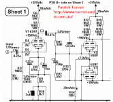
Of course then I found that the Acrosound catalog shows a circuit with plate stoppers there 🙂 Funny there are no screen stoppers though.
An excerpt from --> http://www.tubebooks.org/file_downloads/acrosound.pdf

Realistically though, if someone is designing for ½ a tube, they can easily parallel the sections and just make Rk and Ra ½ their original values, right? 🙂
Or you could use a cathode resistor for each tube and only parallel the plate circuit. Or you could use one cathode resistor and give each tube a plate stopper - both of which can limit current hogging but the plate stopper can also stop the two halves from oscillating with each other.
This happened in an amp I build where I paralleled KT88 tube, and it didn't play nicely until I put in 27R plate resistors.
Of course then I found that the Acrosound catalog shows a circuit with plate stoppers there 🙂 Funny there are no screen stoppers though.
An excerpt from --> http://www.tubebooks.org/file_downloads/acrosound.pdf
- Home
- Amplifiers
- Tubes / Valves
- Unused 12AX7 pins