Hi all,
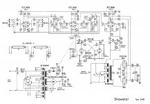
I recently repaired an old echolette showstar S40 guitar tube amplifier (schematic attached) but there are some open questions. The vibrato wasn't working anymore, so I sourced an ORP 62 photo resistor and a 48V bulb somewhere in the US, and along with a new ECC82 the multivibrator circuit works again. I also changed all of the electrolytic caps in the amp. But here is the thing: with the vibrato off I can properly adjust the EL34 bias to whatever i want it to be. However, as soon as I switch the vibrato on, the bias on the power tubes drops by ~almost 10 mA. So I assume that the vibrato circuit is drawing too much power from the bias supply (although it seems to work fine). Does anyone have experience with this amp? is the bias drop maybe normal? Can anyone infer from the schematic what component might be off, or how much current the vibrato should draw? Any help greatly appreciated!!
Cheers, kai
Attachments
What do you mean by the bias dropping almost 10 mA? That the bias voltage gets more negative, so the EL34's draw about 10 mA less, when you switch on the vibrato?
I would expect the opposite (and would than have advised to check C30; if that capacitor would be leaky, it could make the bias less negative when the vibrato is switched on).
Addition: I reacted too fast. Probably the vibrato starts to work when the on/off switch opens, making the negative voltage at C30 disappear. That would fit with what you wrote. So check C30.
Last edited:
Sorry I see that I wasn't clear, I measured bias current over the 1 Ohm resistors, and it drops. Bias voltage increases from ~-36 to -38V. That doesn't make a lot of sense to me.
If C30 is a bit leaky, there would be some current flowing through it coming from the negative supply (marked "4") when the vibrato is switched off. When the vibrato is switched on, this current stops to flow, making the bias go a bit more negative.
There is some current from the negative voltage supply flowing to the multi-vibrator anyway when the vibrato is switched off (than there is a path to ground through R56, R47 and R48), so it could just be the result of the design.
There is some current from the negative voltage supply flowing to the multi-vibrator anyway when the vibrato is switched off (than there is a path to ground through R56, R47 and R48), so it could just be the result of the design.
Last edited:
krank,
Did I miss something in your description?
When EL34 grid bias changes from -36V to -38V, the grid is More Negative.
More Negative grid = Less Cathode Current.
Less Cathode Current = Less voltage across the 1 Ohm Cathode current sense resistor.
That sounds like what you described in Post # 3.
Welcome to the Tubes / Valves portion of diyAudio!
There is also an Instruments & Amps portion of diyAudio, where they discuss guitar amplifiers.
Last edited:
If not obvious, measure EVERY point with and without trem.
Point [4] may be of interest, since EL34 bias and trem osc come together there. If D1 is older than my dog, it may need a freshing.
Point [4] may be of interest, since EL34 bias and trem osc come together there. If D1 is older than my dog, it may need a freshing.
I agree point 4 is of interest, when the tremolo is off some additional current flows through that node to cut off the tremolo oscillator by driving one of the ECC82 sections into cut off. When tremolo is enabled the bias voltage will rise significantly if the diode is a tired old selenium increasing the output stage bias voltage significantly.
Check the resistor values in the tremolo circuit as well.
Check the resistor values in the tremolo circuit as well.
- Home
- Amplifiers
- Tubes / Valves
- 1967 Echolette Showstar refurb