I'm sure this has been covered somewhere but having trouble getting specific guidance on where to place ground reference for center taps using two separate transformers in tube preamp build.
The power transformer HT winding (330-0-330) feeds an EZ81 (indirectly heated) rectifier and I'm using the transformer's 7.2 v winding (has center tap) for feeding the EZ81 filament using a dropping resistor to reach 6.3V.
Since the power transformer's 7.2 winding couldn't handle the combined current of the 6 valves filaments with the rectifier filament, I'm using a hammond 18 volt transformer (has center tap) for feeding the 6 preamp tube filaments. I've read as many forum threads here and there stating to float it as I have stating to ground reference it due to potential noise
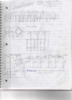
I've included a sketch of the two supplies for reference.
I'll list different options for you to look at and let me know best practice for this so I don't end up taking anything to ground reference needlessly and don't cause other problems.
18 volt filament supply feeding preamp tubes:
-Take center tap to ground bus or cap center tap and take 0 volt leg of bridge rectifier to ground bus?
Power transformer:
-Take center tap 0 volt leg of 330-0-330 winding and reference to ground bus?
-Take center tap of 7.2 volt winding feeding EZ81 filament to ground bus or leave capped?
The power transformer HT winding (330-0-330) feeds an EZ81 (indirectly heated) rectifier and I'm using the transformer's 7.2 v winding (has center tap) for feeding the EZ81 filament using a dropping resistor to reach 6.3V.
Since the power transformer's 7.2 winding couldn't handle the combined current of the 6 valves filaments with the rectifier filament, I'm using a hammond 18 volt transformer (has center tap) for feeding the 6 preamp tube filaments. I've read as many forum threads here and there stating to float it as I have stating to ground reference it due to potential noise
I've included a sketch of the two supplies for reference.
I'll list different options for you to look at and let me know best practice for this so I don't end up taking anything to ground reference needlessly and don't cause other problems.
18 volt filament supply feeding preamp tubes:
-Take center tap to ground bus or cap center tap and take 0 volt leg of bridge rectifier to ground bus?
Power transformer:
-Take center tap 0 volt leg of 330-0-330 winding and reference to ground bus?
-Take center tap of 7.2 volt winding feeding EZ81 filament to ground bus or leave capped?
Attachments
Are any of your preamp audio tubes used as cathode followers, cascodes, or otherwise have
cathodes elevated significantly above ground?
Can you post the preamp schematic?
cathodes elevated significantly above ground?
Can you post the preamp schematic?
Yes on tubes being used as cathode followers. No on cathodes being elevated significantly above ground.
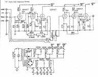
See schematic of the build but I will be including the tone amp from the original Marantz 7C design. Also, disregard the power supply in the schematic and substitute the supplies shown in my post.
See schematic of the build but I will be including the tone amp from the original Marantz 7C design. Also, disregard the power supply in the schematic and substitute the supplies shown in my post.
Attachments
Last edited:
You do have elevated cathodes, so the heater supply should be elevated by about half of the potential of the
cathode follower's cathode. If the CF cathodes are at 120VDC, then elevate the heater supply by 60VDC.
Since the CFs are both a little different, calculate the average of the cathode voltages, and then divide that by 2.
cathode follower's cathode. If the CF cathodes are at 120VDC, then elevate the heater supply by 60VDC.
Since the CFs are both a little different, calculate the average of the cathode voltages, and then divide that by 2.
Last edited:
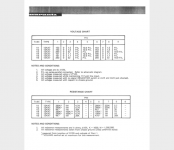
According to the C7 voltage chart (attached), V3 and V6 cathodes are 52 volts which is why I stated no on elevated significantly above ground. Are the numbers shown in their chart referencing differently than the way I should be looking at it?
Let's say I don't need to elevate the heaters, what would be best means for dealing with the issues I raised in the first post:
"18 volt filament supply feeding preamp tubes:
-Take center tap to ground bus or cap center tap and take 0 volt leg of bridge rectifier to ground bus?
Power transformer:
-Take center tap 0 volt leg of 330-0-330 winding and reference to ground bus?
-Take center tap of 7.2 volt winding feeding EZ81 filament to ground bus or leave capped?
Attachments
I would ground only the most negative node of the filaments, but not the filament winding CT.
Of course the HV center tap must be grounded.
If the rectifier's filament is alone on the winding, just connect one end of the filament to the rectifier cathode,
and don't connect the CT.
Of course the HV center tap must be grounded.
If the rectifier's filament is alone on the winding, just connect one end of the filament to the rectifier cathode,
and don't connect the CT.
Last edited:
I would ground only the most negative node of the filaments, but not the filament winding CT.
Understood
Of course the HV center tap must be grounded.
So, take HV common 0 volt leg connected to terminal 9 of the HV winding and make a connection to my ground bus?
If the rectifier's filament is alone on the winding, just connect one end of the filament to the rectifier cathode,
and don't connect the CT.
The rectifier filament is alone on the winding.
So for clarification, connect one end of the rectifier filament to the cathode (terminal 4 to term 3 of the rectifier)?
Attachments

Yes.
Connecting the rectifier's filament to the rectifier's cathode keeps the voltage difference to a minimum,
even though the tube's rating for the difference is 500V.
Connecting the rectifier's filament to the rectifier's cathode keeps the voltage difference to a minimum,
even though the tube's rating for the difference is 500V.
Last edited:
I stated I understood this comment but can you elaborate on where this point is? Not sure why grounding to one or the other end of the filaments return path to the transformer would matter?
"I would ground only the most negative node of the filaments"
"I would ground only the most negative node of the filaments"
"I would ground only the most negative node of the filaments"
Can you describe the connection point where the ground reference would connect to the filaments to be at the most negative node?
Sorry to be so dense but want to get this right and power supply design is challenging to me.
Can you describe the connection point where the ground reference would connect to the filaments to be at the most negative node?
Sorry to be so dense but want to get this right and power supply design is challenging to me.
The same node as the negative terminal of the last filament filter capacitor.
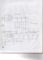
Post your revised circuit here before powering it.
Post your revised circuit here before powering it.
Last edited:
See revised circuit. Let me know if it needs additional tweaks.
Interesting post from another forum on potential transformer winding insulation issues when elevating filament voltage. Anything to be concerned about this? My transformer is a vintage NOS Chicago Transformer typically used in valve audio but never put into service.
When floating filament windings, you need to be aware of the insulation breakdown voltage of that particular transformer winding. Some windings are designed for this purpose such as a 5-volt rectifier filament winding but other windings like 6.3-volt windings may not withstand the elevated floating voltage.
Attachments
See revised circuit. Let me know if it needs additional tweaks.
Interesting post from another forum on potential transformer winding insulation issues when elevating filament voltage. Anything to be concerned about this? My transformer is a vintage NOS Chicago Transformer typically used in valve audio but never put into service.
When floating filament windings, you need to be aware of the insulation breakdown voltage of that particular transformer winding. Some windings are designed for this purpose such as a 5-volt rectifier filament winding but other windings like 6.3-volt windings may not withstand the elevated floating voltage.
After reading the statements on military specs for their transformers I think I'll be ok elevating without concern for winding breakdown.
The Chicago transformer I'm using is the PSC 60 on page 14 in the catalog linked.
http://www.junkbox.com/electronics/Chicago%20Transformers%20Catalog%20ctc-58%201958.pdf
- Home
- Amplifiers
- Power Supplies
- Grounding Questions for preamp build with two separate transformers