Hi guys!
Here I have the headphone amp schematic that came up with and I would like to get some tips from you or maybe even confirmation if you think that it should be a working circuit. As a preamp, I'm using 12AU7(ECC82) and as a output stage WCF with ECC88. It is meant to be able to drive 32 ohm headphones. The first half of the ECC82 acts as a volume control and then the signal goes to eq and then to the second half of ECC82. I really apreciate your help. Thanks.
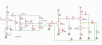
Here I have the headphone amp schematic that came up with and I would like to get some tips from you or maybe even confirmation if you think that it should be a working circuit. As a preamp, I'm using 12AU7(ECC82) and as a output stage WCF with ECC88. It is meant to be able to drive 32 ohm headphones. The first half of the ECC82 acts as a volume control and then the signal goes to eq and then to the second half of ECC82. I really apreciate your help. Thanks.
Attachments
What does ltspice show?
Output impedance will be an issue if you’re not using an output transformer.
Output impedance will be an issue if you’re not using an output transformer.
All coupling caps are 1 uF which is HUGE, and then the output cap is also a tiny (in this place) 1 uF. Cough cough.
Your tone control looks wrong. C19 should be 10uF, no?
.,
If ECC88 doesn't have enough balls, use 6N6P.
What is the Z of your headphones? Your design will probably struggle with 32R but high Z like HD600 or ATH-R70x will be nice. 6N6P instead of ECC88 will improve this a bit.
I would change the cap values to the following:
C1 470uF or so
C4, C8, C6 220nF or so
C7 470uF - 2200uF
Koda
Last edited:
Given an amplifier output stage that is zero ohms output impedance (which an ECC88 is not), and that has flat frequency response from 20Hz to 20,000Hz, Then if you drive a 32 Ohm headphone with a 1 uF output capacitor . . .
A 1 uF output cap is 32 Ohms of capacitive reactance at 5,000Hz.
That means the output is -3dB at 5000Hz, and -1 dB at 20000Hz.
Great for driving a 32 Ohm super-tweeter, but there will not be any midrange, and absolutely no bass.
A 1 uF output cap is 32 Ohms of capacitive reactance at 5,000Hz.
That means the output is -3dB at 5000Hz, and -1 dB at 20000Hz.
Great for driving a 32 Ohm super-tweeter, but there will not be any midrange, and absolutely no bass.
Last edited:
Given an amplifier output stage that is zero ohms output impedance (which an ECC88 is not), and that has flat frequency response from 20Hz to 20,000Hz, Then if you drive a 32 Ohm headphone with a 1 uF output capacitor . . .
A 1 uF output cap is 32 Ohms of capacitive reactance at 5,000Hz.
That means the output is -3dB at 5000Hz, and -1 dB at 20000Hz.
Great for driving a 32 Ohm super-tweeter, but there will not be any midrange, and absolutely no bass.
Precisely.
OP, sorry my answer was a bit cryptic. The bode plot will show you what the frequency response is. It's possible to calculate this by hand and that is a skill worth learning.
0.22uF is my starting point normally for coupling caps if I'm not familiar, also I'd go for something like 4700uF output capacitance to prevent rolloff. However you'd need todo the calculations.
An ECC88 cathode follower output impedance, before applying negative feedback around the driver stage and cathode follower output stage, is aproximately:
1/Gm; in series with plate load, RP divided by (u +1).
u = 33
RP = 120 Ohms
1/12,000 uMhos = 83 Ohms
120 Ohm/ (1+33) = 3.5 Ohms
Cathode follower output impedance = 83 + 3.5 = 86.5 Ohms.
You are using an ECC88 output impedance of about 86 Ohms to drive a 32 Ohm headphone impedance.
The negative feedback will reduce the output impedance, and will tend to flatten out the low frequency roll off of the output capacitor.
But there may not be enough open loop gain versus gain with negative feedback, and not enough output current, to run the 32 Ohm headphone to a loud listening level, and to low distortion, and to not clip at mid and low frequencies when the output level is loud.
Start with an amplifier circuit that works fairly well without any negative feedback, and only then apply negative feedback.
You might prefer the results then; either with negative feedback, or without negative feedback.
Happy designing, Happy building, and Happy listening!
Last edited:
Even with 4 ecc88 triodes in parallel you’re still have ~21ohms output impedance. Then you will find that parallel tubes have larger total miller grid capacitance and the power supply requirements rise.
I'm not sure about the following but is the value of R2 with 1K not too low for applying the NFB to the grid of V2.3?
So the negative feedback is working into the tone control impedance which I don't think was intended. So output gain approx. R20 / (impedance of tone control). Tricky to solve. Since headphone amps only need a closed loop gain of say 3x or so. You could make the first stage just a cathode buffer and reduce the tone control impedances maybe - others may have better ideas.
V1.3 grid is at ground which is wrong.
V1.3 grid is at ground which is wrong.
Last edited:
Personally I would do away with the tone control completely especially given the output impedance it’s not going to make the blindest difference. The output impedance needs addressing first.
OTLs are not the simple cousin of the transformered tube amp when coupled with low impedance headphones.
Start with the back and work forward, if you want NFB then it’ll be planned into the gain. NFB simply attempts to correct the high output impedance (attempting to supply more current to correct the wrong voltage) but isn’t the same as low output impedance. It’s still got to have low enough impedance to allow the current to flow.
.png")
The problem always is without a transformer you waste so much power just to get a 2vppk swing into 32R. What's needed is a low voltage valve with low rp. What about something like a 6H30?
The problem always is without a transformer you waste so much power just to get a 2vppk swing into 32R. What's needed is a low voltage valve with low rp. What about something like a 6H30?
6H30 example here: Aikido 9-pin Low-Impedance Headphone Amplifier
Output impedance 50ohms.
It could paralleled for lower output impedance but it would need some checks.
You could also make this a WCF which would be even better. Interesting hum cancellation. I have a ltspice go later. They do take more heater current.
Last edited:
.png")
I was thinking of 6H30 but no simulation model. They seem to be about £26 each. Just playing with ideas...
Watford Valves :: Valves - 6H30
Watford Valves :: Valves - 6H30
Last edited:
That's more affordable than these LOL 6N30P-DR / 6H30n-DP
Still 6N13S (6AS7G equiv) is even less... 6AS7GA / 6H13C / 6N13S Svetlana / Russia (NOS) and can push more current.
Still 6N13S (6AS7G equiv) is even less... 6AS7GA / 6H13C / 6N13S Svetlana / Russia (NOS) and can push more current.
- Home
- Amplifiers
- Tubes / Valves
- Tube headphone amp design