Hello, any Yamaha A-1 DC coupled specialists out there?
This amp is ‘working’ but Idle Current won’t adjust at all with newly installed Bourns trimpots and is at 1000mV on one channel, 0 mV on the other!
So far, I’ve:
replaced all OT’s with MJ21193/4G
replaced four 330ohm resistors at R 101, 102, 103, 104 with https://uk.farnell.com/multicomp/mf12-330r/res-330r-1-125mw-axial-metal-film/dp/9343032
replaced two fusistors at FR 101, 102 with https://uk.farnell.com/koa-speer-el...-film/dp/3541480?CMP=e-email-sys-orderack-GLB
Are the above replacements all correct?
A hum is present.
Readings:
-DC is 35 V and stable
-Offset DC is 0 mV and ranges +/- 5mV.
DMM on the Electrolytic Cap Board:
Negative lead on TP1
Positive lead on TP 3
Climbs steadily up and down between-500mV to -1060mV
Negative lead on TP2
Positive lead on TP4
Settles on exactly 0mV !
Turning up the volume control (whether ‘Aux button’ with signal and sound is selected, or ‘Tuner button’ with no signal, result is the same) reduces TP1 to TP3 reading closer towards zero mV by about 50%..
The sound through the speakers has some kind of ‘resonance’ running through it, hard to describe but it doesn’t sound right.
Switching from Aux to Tuner (with no source connected) and turning up the volume produces a hum through the speakers.
Any suggestions?
I assume this was broken before you decided to replace outputs? Did the replacement make it start working, or is it acting the same as when you started the repair?
You need go further back from the outputs your replaced. Sounds like a bias transistor is failing on one and failed on the other, or a driver transistor is failed and not providing proper voltage to the bias.
With your DMM start checking (diode mode) if you have any small signal transistors with a short from B-C. B-E and C-E. If you find one faulty, be sure and check resistors around it as they may have draw excess current and gone high value or failed completely. On
Thanks Bullittstang, good questions and suggestions.
Yes, an OT was failing and causing problems.
It’s working a bit more consistently now, but the inability to adjust idling current was a problem before.
I’ll try to check the transistors and resistors you mentioned later on.
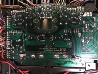
In the meantime I’ll try to upload some photos. Might you be able to highlight or point out the most likely suspects?
Thanks again.
Yes, an OT was failing and causing problems.
It’s working a bit more consistently now, but the inability to adjust idling current was a problem before.
I’ll try to check the transistors and resistors you mentioned later on.
In the meantime I’ll try to upload some photos. Might you be able to highlight or point out the most likely suspects?
Thanks again.
T
Attachments
-
 8C1AA990-B55E-4655-B631-CA82038EA873.jpeg826.9 KB · Views: 245
 -
 845284EC-455C-4037-9878-504D82C3373D.jpg486.3 KB · Views: 245
 -
 9B987E88-D21F-4930-8995-673D01FCA9F6.jpeg814.6 KB · Views: 247
 -
 3D597186-DC1E-4FB3-ADCC-71960AFB5E83.jpeg422.1 KB · Views: 253
 -
 13E49BAA-63A7-4179-9F4A-DA4C32C3AB80.jpeg284.3 KB · Views: 244
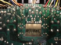
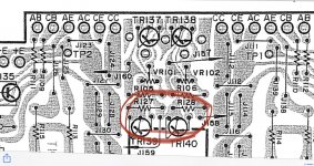
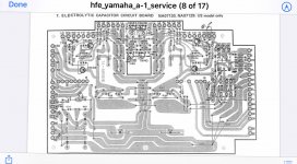
Does the area in the middle of the board near to R127 and R128 and the two transistors TR139 and TR140 appear different to the layout drawing? I think that there’s an enlarged solder blob covering three points?
Can this be done with the amp powered off?
Can this be done with the transistors and resistors in situ?
“ With your DMM start checking (diode mode) if you have any small signal transistors with a short from B-C. B-E and C-E. If you find one faulty, be sure and check resistors around it as they may have draw excess current and gone high value or failed completely.”
Yes, see my answer in your other post with same question for the caveats to this yes.
Also - Google is you friend and you will find lots of videos on testing both in and out of circuit with a DMM
Also - Google is you friend and you will find lots of videos on testing both in and out of circuit with a DMM
it's pretty funny because this amp is not very common, but we just brought me two at the workshop.
I started the first one yesterday morning and what emerges is that if you have changed the eight 330ohm and the two 68ohm 60mA fuse resistors, you have a problem with the driver board.
recheck also all of the A913 and C1913.
moreover, the welds on this amp are really misleading, I undertook to redo all of them temporarily before looking for faults because there is nothing worse than ending up with faults that appear and disappear.
you can also automatically control the 2sk100 which can die very easily.
really, if you don't have any real skills in electronic troubleshooting, give it up and take it to a professional.
I don't have time to guide you for this repair, otherwise I would have done it with pleasure.
if however you persist, check the entire driver board (solders, resistors and transistors)
I don't have time to guide you for this repair, otherwise I would have done it with pleasure.
if however you persist, check the entire driver board (solders, resistors and transistors)
Thanks Huggygood, nice advice. And you’re in ‘Brittany‘ it appears, I had so many good holidays there, just like our Cornwall I thought but on steroids and lots more space.
Anyway, this amp..
I’ll check the Driver board’s components, although it’s a real surprise to me that a fault here could possibly mess up the idling current adjustments, but thankyou for the advice. Please let me know of any further clues or if you discover something else while doing your twin repairs.
The 330 ohm ones, just 4 of them I think, should I replace with carbon or metal film?
I’ve already put a huge amount of time into this amp and feel very close to success, especially as it plays and stays on, just these last little faults in the way..
Have managed to restore a Yamaha CR1020 and a P2200 but still learning...and this A-1 feels like the hardest lesson.
“ recheck also all of the A913 and C1913.”
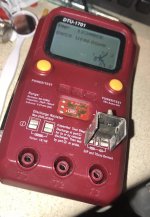
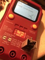
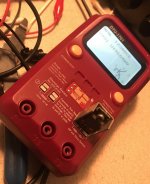
With a cheap transistor tester, do the readings in these photos seem good?
With a cheap transistor tester, do the readings in these photos seem good?
Attachments
Seen from here it looks correct.
do you have the schematic of the amp?
have you checked the four 47ohm that I indicated to you on the photo?
have you checked TR 137 138 139 140?
and yes I have been in Brittany for about 20 years, I settled there after having tried several places in France and Europe but I also really like the UK and Ireland (my ex-girlfriend is Irish)
I have one of those parts testers, mainly for use with SMDs though it also has some unusual and good features. Unfortunately, it comes fitted with what must be about the world's worst LCD display which seems to have all the old screen faults from the 1970s in the one gadget.
Thanks guys.Yes, Ian, fair review of the instrument.. and it’s very nicely priced too.
Huggygood, thanks for asking and, yes, looking again at the four 5W 0.47ohm emitter resistors one is open so have ordered a couple of replacements so that both channels match.
“have you checked TR 137 138 139 140”
TR137
2sc1213A(positioned back to front)
BE I
BC I
EB 618
CB 614
EC I
CE I
TR138
BE I
BC I
EB 612
CB 612
EC I
CE I
TR 139
A708 13CCY
BE 846
BC 1296
EB 588
CB 626
EC 761
CE 626
TR 140
A708 13CCY
669
BC 1143
EB 601
CB 590
EC 762
CE 562
Thanks to your recommendation to look more closely at the Drive Board I discovered something else!
R555,556 and R561,562 have had a previous repair.
2 photos attached below.
The SM say they should all be 1.5Kohms
In circuit they all read about 760 ohms, EXCEPT R555 which reads 1.5Kohms
Should I replace all of them?
And with just standard 250mW 1.5Kohm carbon film resistors?
"recheck also all of the A913 and C1913.”
Below are the in-circuit readings, please could you let me know if they look ok?
If they need replacement, please can you recommend what’s best?
TR 135
2sa913
BE 590
BC586
EB I
CB I
EC 506(climbs)
CE 1250(climbs)
TR 133
2scv1913
BE I
BC I
EB 576
CB 520 (climbs)
EC 1100 ((climbs)
CE 525
TR 136
2sa913
BE 590
BC 584
EB 1960 (climbs to I)
CB I EC 524
CE 1300 (climbs)
The Drive board’s TR 525, 526, 527, 528 in circuit read:
Anything look suspicious?
TR 528
2sc1953
BE I
BC 1945
EB 689
CB 672
EC 1760 moving
CE I
TR526
2SA914
BE 674
BC641
EB I
CB I
EC I
CE 1822
TR 527
2sc1953
BE I
BC I
EB 689
CB 672
EC 1780 moving
CE I
TR525
2sa914
BE 690
BC 670
EB I
CB 1956
EC I
CE 1735
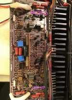
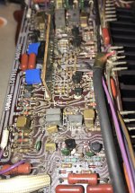
photo 2, just below the two resistors you have two diodes, unsolder them and check them.
I have to leave, I will be back tomorrow afternoon, I will look at the rest at that time.
on the main pcb (na7039) controls the four 4,7r 1 / 4w at the edge of the pcb on the right, seen from above.
I just made mine work on one channel and the other channel is on track but it is impossible to stick the protection relay, this device is a hassle ...
Thanks for the comments, much appreciated, and look forward to catching up tomorrow.
The diodes are good I think, both measure 'I' and then '618.'
"on the main pcb (na7039) controls the four 4,7r 1 / 4w at the edge of the pcb on the right, seen from above."
I believe you mean R109,110,111,112. Yes, and I believe I have a faulty or wrong spec resistor at R109.
SM says 4.7 ohms, Ok to replace with 250mW these ?
https://uk.farnell.com/koa-speer-el...7j/res-4r7-0-25w-axial-carbon-film/dp/3540679
Last edited:
A guy called Johannes on another forum sent a link to this diagram which might be of help:
Yamaha A 1 Schematic Detail Left Power Amp Stages Marked | yamahaa1schematicdetailleftpower | hifi-forum.de Bildergalerie
Yamaha A 1 Schematic Detail Left Power Amp Stages Marked | yamahaa1schematicdetailleftpower | hifi-forum.de Bildergalerie
- Home
- Amplifiers
- Solid State
- Yamaha A-1 idle current issue