Hi all
Some hesitation on adding to the pile of Sony V-Fet threads. So this is aimed at logging MY refurbishment of a Sony TA-5650.
(My TA-4650 thread is https://www.diyaudio.com/forums/solid-state/376634-sony-ta-4650-fet-thread.html that didn't actually go so well)
First of all lets get some resources out of the way (just in case)
Service manual: best copy by far I've found is at hifiengine although others exist they are resolutely monochrome 🙁
Service bulletins: yes! most important is the 'dutch' one as it details mods to bias and component changes made to enhance longevity (Has ANYONE seen that in English?)
Circuit operation: see "Sony TA-4650 new circuit operation" for a how it works document that broadly applies
Other links:
https://www.diyaudio.com/forums/solid-state/311612-sony-ta-5650-restoration-doc-breaths-life.html
What I hope this thread will mimic 🙂
So here goes, as usual I haven't finished this project yet so its not a tale of, "this is how you" it's recorded live 😀
I find it very useful to step away from the project and document it.
I have *TWO* Sony TA-5650 amps and one set of working power transistors
Serial 601467 - marked as 601518 internally
Serial 602370 - marked as 300378 internally
602370 has Grey Elna Caps fitted rather than blue Nichicon ones, as a side note, it is also missing a positive power rail, at least without Vfets
To me it looks like 602370 went back at some point and got a new serial (?!?) Unless someone knows what the internal numbers actually mean anyway...
601467 is cleaner, as both of these are 'pre-loved' maybe it's been serviced, I couldn't tell you. Anyway I'm going with 601467 from here in. A decision that would have been best made BEFORE I robbed the output board for the TA-4650 project.
Can I just say I hate wire wrapping. I really hate wire wrapping.
Andy
Attachments
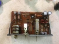
Power supply Caps
One obvious starting place is the PSU caps. Nowadays I just write these off as dead on any equipment this age. Too many times I've been astounded once they were replaced. Working, is not the same as WORKING
Of course 'Sony' and 'time' have intervened to make no direct replacement available, so I use Kemet 10,000uf - I used RS type 189-797. If you have access to a 3d printer the STL file for the adaptor is attached. if not, tape works I guess. You may need to tickle the fitting too 🙂
However, at the time of writing there seem to be options, all from Kemet
RS189-787
RS144-3389
RS381-9100
Well I've got the former so that's what I'm using, one thing about replacing 30+yr old caps is I'm pretty sure, no matter what, it's hard to make it worse.
but do check the lead pitch
Andy
Attachments

Board one
So here we go...
The output board. Yes, OK, starting at the end, but it's simple and I need to get the bits I have from two amps back together to make one semi-coherent mess.
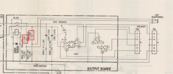
For the first time burned resistors! which was a surprise, one half of the potential divider chain got cooked (R901 and R951) , so I guess this comes from low impedence headphones or something??? To be replaced anyway - RS 125-1158 for all four.
Then there is the tricky situation of the output relay. On this occasion I've decided to swap it, but that's only because it feels like I should in light of the resistors. It's quite an expensive part at nearly £10+tax. However RS 245-2273
Andy
So here we go...
The output board. Yes, OK, starting at the end, but it's simple and I need to get the bits I have from two amps back together to make one semi-coherent mess.
For the first time burned resistors! which was a surprise, one half of the potential divider chain got cooked (R901 and R951) , so I guess this comes from low impedence headphones or something??? To be replaced anyway - RS 125-1158 for all four.
Then there is the tricky situation of the output relay. On this occasion I've decided to swap it, but that's only because it feels like I should in light of the resistors. It's quite an expensive part at nearly £10+tax. However RS 245-2273
Andy
Attachments
So here we go...
The output board. Yes, OK, starting at the end, but it's simple and I need to get the bits I have from two amps back together to make one semi-coherent mess.
For the first time burned resistors! which was a surprise, one half of the potential divider chain got cooked (R901 and R951) , so I guess this comes from low impedence headphones or something??? To be replaced anyway - RS 125-1158 for all four.
Then there is the tricky situation of the output relay. On this occasion I've decided to swap it, but that's only because it feels like I should in light of the resistors. It's quite an expensive part at nearly £10+tax. However RS 245-2273
Andy
My 5650 had exactly the same issue with burned resistors on the same board. Must be a common fault.
Jon
I've seen it (the burned resistors) mentioned before but 2/3 has been OK so far my punt is "modern" low impedance headphones. Anyway more 'robust' items should solve the problem 2W items for example AKA 'you can't overkill it too much' or at least hopefully
Andy
Andy
Attachments
Service manual incorrect?
I've unfortunately found myself missing some caps on this one. But in the course of running through the parts list in the service manual vs reality there's a *real* oddity
Equalizer [sic] amp board:
C255 and C205 are listed as 10uF at 50V. But *no* they are 10uf at 100v
They are supposed to have no more than 20v across them. Odd Sony choice due to availability or what?
I'm (re)reading the schematic now and essentially deciding they need to be film caps though - thoughts?
Andy
Attachments
I did not touch the caps on the pre-amp or mixer boards, they all seemed fine, but have an itch to replace all signal path Caps with film equivalents.
That TA-4650 I scored has now been stripped, cleaned, diodes replaced, balance mod done, main board recap, bias trim posts replaced and then set-up and tested. All good, working fine. Next is to upgrade to binding posts and then test vs the 5650.
Jon
That TA-4650 I scored has now been stripped, cleaned, diodes replaced, balance mod done, main board recap, bias trim posts replaced and then set-up and tested. All good, working fine. Next is to upgrade to binding posts and then test vs the 5650.
Jon
Ah that makes sense...
So,
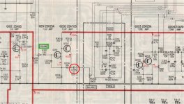
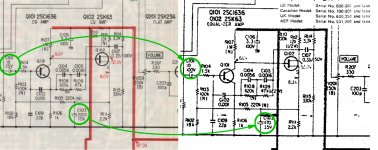
Just in case anyone else has the same puzzled face, I figured out why the Sony SM I've been referring to is sometimes erroneous. The *Good* quality version is effectively V1 the 'less good' quality versions show the changes from later serial numbers on a separate page.
This does bear looking into esp if you are using the Phono stage, I'm guessing all done to aid reliability of the 'other' V-fets? Although it's a heck of a source to require 100v dc blocking through C101/C151 😱
Incidentally same applies to C205 and C255 was 50V part; then 100V. so something ELSE to keep an eye out or if you have an early amp
Andy
So,
Just in case anyone else has the same puzzled face, I figured out why the Sony SM I've been referring to is sometimes erroneous. The *Good* quality version is effectively V1 the 'less good' quality versions show the changes from later serial numbers on a separate page.
This does bear looking into esp if you are using the Phono stage, I'm guessing all done to aid reliability of the 'other' V-fets? Although it's a heck of a source to require 100v dc blocking through C101/C151 😱
Incidentally same applies to C205 and C255 was 50V part; then 100V. so something ELSE to keep an eye out or if you have an early amp
Andy
Attachments
More updates:
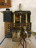
Volume control board / Phono amp
10uF electrolytics replaced with 10uF poly and 470Uf caps also replaced
I took the volume pot out entirely to clean it, so we'll see how that worked later. I am so DONE with scratchy volume controls.
The 250k resistance for the volume pot was about 270k on the best one of two, and +/-10% between channels at best. So I guess don't worry if one channel is off to the other?
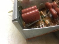
C101 and C151 were tricky to fiddle because of the danger of shorts - little bit pleased (on the second attempt) with how that turned out. Stash them above the resistors...
Completed:
- Function selector board
- Tone control board
- Output board
- Equalizer amp board
almost:
- Filter board
- Rectifier board
Not started:
- Amplifier board
Andy
Volume control board / Phono amp
10uF electrolytics replaced with 10uF poly and 470Uf caps also replaced
I took the volume pot out entirely to clean it, so we'll see how that worked later. I am so DONE with scratchy volume controls.
The 250k resistance for the volume pot was about 270k on the best one of two, and +/-10% between channels at best. So I guess don't worry if one channel is off to the other?
C101 and C151 were tricky to fiddle because of the danger of shorts - little bit pleased (on the second attempt) with how that turned out. Stash them above the resistors...
Completed:
- Function selector board
- Tone control board
- Output board
- Equalizer amp board
almost:
- Filter board
- Rectifier board
Not started:
- Amplifier board
Andy
Attachments
Looks good, please post the part numbers when you have time.
I noticed my volume pot is very slightly scratchy but had only cleaned with servisol in situ.
I noticed my volume pot is very slightly scratchy but had only cleaned with servisol in situ.
update #1
I think you mean the 10uF Caps? they were RS No 808-3441 Panasonic types. Somewhat compromised (?) by the need to get them to fit - but it has to be said that the pre-amp output caps have tonnes of room, so your mileage may vary.
Scratchy vol pot - Unless you wince when you change the volume it's probably OK 😀
Andy
Looks good, please post the part numbers when you have time.
I noticed my volume pot is very slightly scratchy but had only cleaned with servisol in situ.
I think you mean the 10uF Caps? they were RS No 808-3441 Panasonic types. Somewhat compromised (?) by the need to get them to fit - but it has to be said that the pre-amp output caps have tonnes of room, so your mileage may vary.
Scratchy vol pot - Unless you wince when you change the volume it's probably OK 😀
Andy
Update #2
More then
All boards except for amp board finished and got me a wire wrapping tool from Digikey: K743-ND - Jonard tools JIC-22681
Yeah that's a thing! It works very, very well
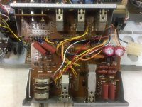
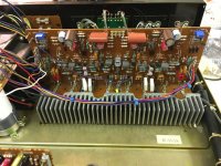
However, the cleaning of the amp board really fought me - lots of white nastiness after the IPA, quite a lot of flux residue beforehand but nasty, ohhh NASTY. Spent hours between drying and scrubbing but finally a clean board.
Andy
More then
All boards except for amp board finished and got me a wire wrapping tool from Digikey: K743-ND - Jonard tools JIC-22681
Yeah that's a thing! It works very, very well
However, the cleaning of the amp board really fought me - lots of white nastiness after the IPA, quite a lot of flux residue beforehand but nasty, ohhh NASTY. Spent hours between drying and scrubbing but finally a clean board.
Andy
Ah then there's this little problem.
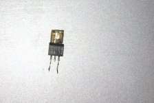
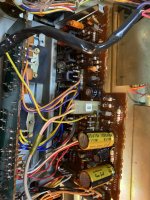
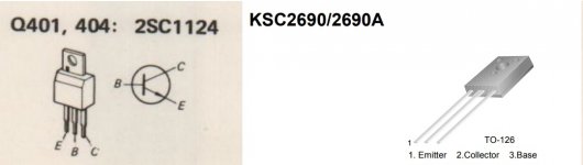
Just checking everything over - fiddling basically, and happened to touch Q401 and thought "that's a bit wiggly" and it was too. :/
I do have some spare 2SC1124 from the donor amp, but in searching for equivalents it's been labelled as unreliable and to use SC2690A instead
Probably ought to swap out the other 2SC1124 on that board while I'm at it?
Thoughts anyone?? I'm bumbling off back to the TA4650 in the meantime...
Attachments
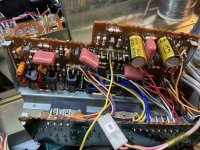
Andy, please check the positioning of the 10uf caps on the power amp board. The fittings for the board support and chimneys may foul the caps as you have them.
That's a good point! - I took two of them off, this amp is not going off-roading. The chimneys are pretty robust and the board is supported at either end to prevent movement. I suppose you could modify the chimney to support the board with a short bracket but it seems fine to me.Andy, please check the positioning of the 10uf caps on the power amp board. The fittings for the board support and chimneys may foul the caps as you have them.
But yes, chimney mods needed. Photo's to follow.
Andy
I fitted my film caps today so was looking at your photos. I mounted mine vertically, one leg bent close to the body of the cap and then 90 degrees away at the 2nd leg. This gives you one long and one very short leg that can be spaced appropriately and puts the capacitor over the resistors.That's a good point! - I took two of them off, this amp is not going off-roading. The chimneys are pretty robust and the board is supported at either end to prevent movement. I suppose you could modify the chimney to support the board with a short bracket but it seems fine to me.
But yes, chimney mods needed. Photo's to follow.
Andy
just listening to it now and it does sound clearer than with the electrolytics there. I have a few more on the tone board to swap over when the supply arrives next week.
Fitted the rest of the film caps yesterday. It does make a bit of a difference to the sound so will do the same on the 4650 and then make a comparison between the two to decide on my preference.
Attachments

Wait a minute -WOT??
More 'fun'. Again from the school of checking vs advice! the KSC2690 is NOT compatible with the offending Sony 2SC1124 (despite of being listed as such in much more than one place...)
Foolishly, I had assumed that equivalence meant it was more than just electrically similar. I'm not keen on the leg spaghetti to 'make' it fit
Has anyone got an actual datasheet for the 2SC1124, getting a 'mite' frustrated with Googling rabbit holes that lead you to a completely different part
in fact whilst I have the begging bowl out, if there's a decent 2SK60/2SJ18 datasheet then, yes that too 🙂
Andy
Attachments
Soooo As it turns out I'm a bit of an Idiot (if my other posts haven't confirmed that already) Took the SC2690's out and replaced with more original 2SC1124s
same problem R411 IMMEDIATELY smokes - i'm getting real handy with the power switch now. This of course makes no sense until (after some time) I pull apart the bones of the donor amp to find that the connector on the right is tight AND THE OTHER WAY UP!!!
Not at all sure that cursing is approved of in this forum so I wont however 'oh bother, what an unfortunate turn of affairs' more or less sums up the next few moments. I can confirm, a direct short to earth will cause all kinds of mischief
Followed by a realisation that although the 2690's didn't work originally there may be hope yet
I also realised that I didn't right up my power board mods at this point do more posts
- Home
- Amplifiers
- Solid State
- Complimentary ramblings AKA another Sony TA-5650 V-Fet thread