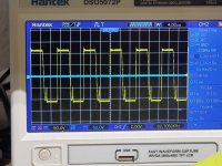
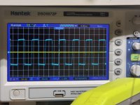
Do the high and low-side signals look the same for both ICs?
Drive signals are best viewed in differential mode with DC coupling.
Drive signals are best viewed in differential mode with DC coupling.
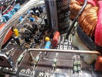
Pull the driver transistors for the hot set of FETs and check them carefully, including for leakage and open junctions.
It's like checking on diode-check but on resistance. After checking the transistor on diode-check, confirming that all junctions are normal, switch to ohms and check the transistor, (reversing the probes) to confirm that you read no leakage (the meter display should remain as it is when the leads are in contact with nothing).
Does the board show any heat stress (rough solder, darkened board/silkscreen...) around any of the drivers?
Does the board show any heat stress (rough solder, darkened board/silkscreen...) around any of the drivers?
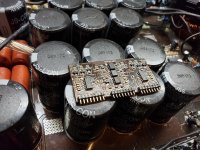
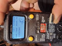
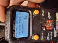
So I got this amp working now but im a little confused. I have one batch of 24n50 fets that read as fets. I have another batch of 24n50's that read as igbt's. Running the batch that reads as fets runs hot but the igbt's run stone cold. Anyone know why that is?
On both ohms and diode-check, what do you read from leg 1 to leg 3 on the parts that read differently?
Check then reverse probes and check again. 4 values.
Check then reverse probes and check again. 4 values.
Use your multimeter.
Check out of the circuit.
It's rarely definitive when checking for leakage when the parts are in the circuit.
Check out of the circuit.
It's rarely definitive when checking for leakage when the parts are in the circuit.
Well, I don't know enough about IGBTs to go further on that part of the repair. I'd suggest asking in the class D forum of this site.
Did you check the drivers as suggested in post #9?
Did you check the drivers as suggested in post #9?
- Home
- General Interest
- Car Audio
- Deep Hitters 9k (Zenon Board)