Hello,
Fixed my Nak CA-7A preamp balance pot and broke something in the phono stage in the process so the sound is now distorted. Looking for help.
EDIT: this problem was due to swapping +35 and +9.2 V power supply rails. However, the right channel head amp suffered damages due to the swapping- see post #6.
The Nak worked well including both MC and MM phono until ~this August when balance pot began to act up then sound from the left channel disappeared. Took it apart and gave balance and tone pots (which actually are stepped attenuators) a good Deoxit cleaning. This fixed the problem with dead left channel. Also, re-checked the MC, MM and Line amps offset adjustments-these were slightly off but I got them to spec.
Attempted to fix another problem- if tone control is engaged, slight hum from the left channel is heard if low or middle tone controls were rotated past 12 o'clock to the right. Checked all connectors to and from the tone control PCB, found nothing wrong and re-flowed their PCB connections as a precaution.
When tested preamp in the system, sound from phono input is distorted with no bass and lower middle at all. This was with both MC and MM cartridges; the Nak never did this before. The signal from line inputs, tuner and tape, was perfectly fine with good bass and lower middle.
Checked offset adjustments: MC was fine; however, the MM amp offset, measured at the pin 7 of IC 102 (L. Ch.)/IC 202 (R. Ch.) is way off: -9.1 VOLTS Left/ -8.9 volts Right and insensitive to the adjusting by VR102/202 pots in either channel. The service manual calls for IC 102/202 pin 7 voltage at 10 mV (millivolts) and it was very sensitive to the VR 102/202 pot rotation. Importantly, I could set it at 10mV before attempting to fix the tone control hum. This IC 102/202 is not in the signal path but rather some kind of controller. The MC phono stage works as a head amp feeding signal to MM; this explains why both MM and MC sound bad.
So, I apparently damaged something in the phono preamp section during the "repair" process. All of the re-flowed connections were checked; fuses are fine, and the line amp sounds fine. What that could be?
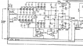
Schematics is attached. Any help will be greatly appreciated.
Fixed my Nak CA-7A preamp balance pot and broke something in the phono stage in the process so the sound is now distorted. Looking for help.
EDIT: this problem was due to swapping +35 and +9.2 V power supply rails. However, the right channel head amp suffered damages due to the swapping- see post #6.
The Nak worked well including both MC and MM phono until ~this August when balance pot began to act up then sound from the left channel disappeared. Took it apart and gave balance and tone pots (which actually are stepped attenuators) a good Deoxit cleaning. This fixed the problem with dead left channel. Also, re-checked the MC, MM and Line amps offset adjustments-these were slightly off but I got them to spec.
Attempted to fix another problem- if tone control is engaged, slight hum from the left channel is heard if low or middle tone controls were rotated past 12 o'clock to the right. Checked all connectors to and from the tone control PCB, found nothing wrong and re-flowed their PCB connections as a precaution.
When tested preamp in the system, sound from phono input is distorted with no bass and lower middle at all. This was with both MC and MM cartridges; the Nak never did this before. The signal from line inputs, tuner and tape, was perfectly fine with good bass and lower middle.
Checked offset adjustments: MC was fine; however, the MM amp offset, measured at the pin 7 of IC 102 (L. Ch.)/IC 202 (R. Ch.) is way off: -9.1 VOLTS Left/ -8.9 volts Right and insensitive to the adjusting by VR102/202 pots in either channel. The service manual calls for IC 102/202 pin 7 voltage at 10 mV (millivolts) and it was very sensitive to the VR 102/202 pot rotation. Importantly, I could set it at 10mV before attempting to fix the tone control hum. This IC 102/202 is not in the signal path but rather some kind of controller. The MC phono stage works as a head amp feeding signal to MM; this explains why both MM and MC sound bad.
So, I apparently damaged something in the phono preamp section during the "repair" process. All of the re-flowed connections were checked; fuses are fine, and the line amp sounds fine. What that could be?
Schematics is attached. Any help will be greatly appreciated.
Attachments
Last edited:
Yes. The +35 and +9.2 volts rails appeared to be swapped! Checked it several times and didn't catch back then. Probably just was a bad day.
This leaves the problem of the tone control hum which heard only if I try to enhance lows or mids and is in left channel only.
This leaves the problem of the tone control hum which heard only if I try to enhance lows or mids and is in left channel only.
I think this is a clear giveaway where the issue is:
Attempted to fix another problem- if tone control is engaged, slight hum from the left channel is heard if low or middle tone controls were rotated past 12 o'clock to the right. Checked all connectors to and from the tone control PCB, found nothing wrong and re-flowed their PCB connections as a precaution.
When tested preamp in the system, sound from phono input is distorted with no bass and lower middle at all. This was with both MC and MM cartridges; the Nak never did this before. The signal from line inputs, tuner and tape, was perfectly fine with good bass and lower middle.
This is a no-brainer, really.
Jan
Apparently, the accidental swapping of +35 and +9.2 V rails did damage the Nak: I can't set up the MC head amp in the right channel to +/- 50 mV with VR201. Previously, that could be easily achieved. Now, it's -120 mV or so at the best and doesn't go to 0 mV with VR 201 turned all the way clockwise.
Measure voltages around and compare with schematics:
+9V rail; anode of D202=collector of Q226/Q266 is +9.28V vs. expected +9V;
-9V rail, cathode of D203=collector Q227/Q267 is-9.26V vs. expected -9V;
IC 201 pin 4=emitter of Q227/Q267 is -6.8V vs. expected -6V;
IC201 pin 8= emitter of Q226/Q266 is+5.9V vs. expected +6V;
ZD 202 anode =-67 mV, cathode =-7.4V
So, both + and -9 V rails deliver voltages as expected; however, the -6 V regulator Q223/Q227/Q267 delivers -6.8V instead of -6V while the +6V regulator is almost on the spot. The -6.8V goes to VR 201 through R222 (499 Ohm, voltage drop across it is 2.38V); the VR 201 input is too negative that’s why I can’t set it to 0 mV. Could it be the problem and if yes, how to fix it?
I suspect that Q225 or Q223 may be shorted C-E, as ZD202 seems to be running at excessive current. Also check D203-204 for shorts (D201-202 won't hurt), as well as R244.
The problem has to be somewhere in the -6 V regulator - the balance adjustment is not going to work properly until its voltage is back in spec. You may have to check every single component, of which there thankfully aren't that many.
The problem has to be somewhere in the -6 V regulator - the balance adjustment is not going to work properly until its voltage is back in spec. You may have to check every single component, of which there thankfully aren't that many.
Finally, got back to this thing:
Checked D201-D204 off circuit, removing one leg: all fine, not shorted or opened, voltage drop is around 0.69 V.
Checked R244 the same way- fine, 17.5 K vs. 17.4 K as in SM.
Soldered out Q225, 2 SC 2440 -fine off-circuit. Replace it with a new 2SC2240 I had just in case. However, the replacement of Q225 didn't fix the problem.
The Q223 is a N-channel JFET, 2SK 170 and I don't have a replacement. Checked it for shorts under an assumption that the shorted one has zero resistance between its outputs in circuit. Didn't find any pairs of outputs with zero resistance for Q223 as well as Q227 and Q267.
However, the resistance between S and D of Q223 is just 50 Ohm while it should be much higher by schematics. Does this mean Q223 is shorted?
Attachments
Q223 is a sort of reference to common ground. It prevents the internal regulator circuit current from entering the ground system and passes it to the opposite supply. It will be a few hundred mV off ground, so that isn't a big deal. The supply voltages (+/- 6 VDC) are not expected to be exact, on the money. What they are expected to be is stable and in the ballpark.
Another 2SK170 would do fine in the same Idss range. If you are reading 50R D-S, it is defective. You'll have to hunt down another, but a replacement from Linear Systems would be fine. Meeting minimum order might be the highest expense. At Digikey you may have access as it is a "Marketplace" item. Ordering direct from Linear Systems is also a good option.
-Chris
Soldered out 2SK 170 (Q223) and measured it with the DMM in the Ohmmeter mode. Before measurements, shorted JFETs terminals.
- to G, + to D or S: OL in both cases;
+to G, - to D: 15.2 MOhm
+ to G, - to S: 15.4 MOhm;
- to S, + to D: 46 Ohm;
- to S, + to G: 14 MOhm.
Looks like it's defective.
The writing on the case is: K170 BL7D. According to the Toshiba datasheet, BL means Idss =6.0~12 mA.
The DIYaudio store offers LSK170 quads with Idss 6-8 and 8-11 mA and I sent them a message. Hopefully they have something.
Last edited:
Hi Andrei,
I think you have the problem on the run. Good luck, and please tell us how it goes.
-Chris
I think you have the problem on the run. Good luck, and please tell us how it goes.
-Chris
Got the LSK 170 JFETs and replaced the dead 2SK 170 with one. Pin output is the same so it's just a drop-in.
Unfortunately, this didn't fix the problem: the voltage is -320 mV if VR 201 is fully clockwise. As before, rotating it the other way lowers the voltage even more. Before replacements, it stabilized at approximately -130 mV.
Unfortunately, this didn't fix the problem: the voltage is -320 mV if VR 201 is fully clockwise. As before, rotating it the other way lowers the voltage even more. Before replacements, it stabilized at approximately -130 mV.
- Home
- Amplifiers
- Solid State
- Nakamichi CA-7A phono stage problem