Amp turns on and plays audio but at a reduced level. Goes into protection when input level is raised. Amp has signs of heat and a burnt resistor on the input board. Replaced the burnt resistor but problem is obviously still present since I didn't repair the cause. Any help on where to start would be greatly appreciated
Photos of the problem areas you mentioned?
Is the problem when the gain control is rotated more clockwise or is it when the output reaches a given level (to the speakers) regardless of the gain control's position?
Is the problem when the gain control is rotated more clockwise or is it when the output reaches a given level (to the speakers) regardless of the gain control's position?
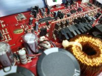
Low output problem is there constantly regardless of the gain position or the input level. Also sounds a little distorted. Amp will only go into protection when the input level is raised (RCA input level). That happens regardless of where the gain position is set to. I have access to an oscilloscope and function generator for testing. I have electronic knowledge but am not very familiar with amplifier circuits. I will attach a picture of the input board with the burnt resistor. Thank you Perry for helping out. All testing so far has been done in a vehicle with known good wiring.
That resistor normally runs very hot. It's typically a 10k ohm 1/8w. The 1/4w should survive. Was it actually burned and far out of tolerance?
The class D driver board components run very hot. This the fan in that configuration, it's likely even worse. For the large transistors on that board, you need to remove them. Desolder the transistor terminals and the solder pads (while the transistors are out of the circuit) and then reinstall them. The solder joints fail and it's sometimes difficult to see the breaks. Moving the tops of the transistors while looking at the connections 'sometimes' makes broken connections easier to see.
The class D driver board components run very hot. This the fan in that configuration, it's likely even worse. For the large transistors on that board, you need to remove them. Desolder the transistor terminals and the solder pads (while the transistors are out of the circuit) and then reinstall them. The solder joints fail and it's sometimes difficult to see the breaks. Moving the tops of the transistors while looking at the connections 'sometimes' makes broken connections easier to see.
Thanks Perry I will remove those and reinstall. I was curious about cold solder joints from the heat. I also found the 7815 to be putting out 24V instead of 15V. The 7915 is putting out the -15V. I replaced the 7815 but there was little change (21V output).
Found R66 to be burnt. Might be part of the 15V regulator circuit. Cannot read the color bands for a value. It is located next to the 7815. I will post a picture.
Measure the output with the black probe on the center leg of the regulator and the red probe on leg 3?
Also measure the input voltage on leg 1.
Also measure the input voltage on leg 1.
15V regulator:
Pin 1: 24V
Pin 2: Gnd ( speaker neg)
Pin 3: 21V
Replaced with a new part (not old stock) and I now have 15V on pin 3.
Original problem of low power output is still present.
Took a few other readings:
Rail voltages:
79V
-79V
Measured at the rectifiers and the output transistors.
Seems low for 2500W.
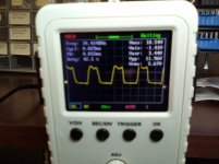
PWM:
10V square wave out of pins 11 and 14.
Not a true square wave but could be my cheap scope.
I will upload the image.
Same 10V signal on the gate resistors
Pin 1: 24V
Pin 2: Gnd ( speaker neg)
Pin 3: 21V
Replaced with a new part (not old stock) and I now have 15V on pin 3.
Original problem of low power output is still present.
Took a few other readings:
Rail voltages:
79V
-79V
Measured at the rectifiers and the output transistors.
Seems low for 2500W.
PWM:
10V square wave out of pins 11 and 14.
Not a true square wave but could be my cheap scope.
I will upload the image.
Same 10V signal on the gate resistors
There is a resistor standing on the main board near the top right corner of the image you posted in post #4. What does it read (out of the circuit)?
There are two resistors standing in the corner. One is R66 (left) and the other is R67 (right). R66 is burnt and the color bands are unreadable. I will remove these and post the values.
Both resistor's measure 6.7K out of the circuit. R67 has a color band of blue, gray, red, and gold. 6.8K. Color bands on R66 are unreadable.
http://www.bcae1.com/temp/classDtype2wdriverboardindexa998.pdf
Seeing the circuit board designations for those resistors makes the amp look like the one above.
What is the marked value of R69 and R70?
I'd recommend lifting and measuring the value of R70.
Seeing the circuit board designations for those resistors makes the amp look like the one above.
What is the marked value of R69 and R70?
I'd recommend lifting and measuring the value of R70.
R69 measures 2.7K and has color band of:
Red, gray, red, gold. 2.8K
R70 measures 147K and has a color band of:
Brown, green, yellow, gold. 150K
Measured out of circuit
Red, gray, red, gold. 2.8K
R70 measures 147K and has a color band of:
Brown, green, yellow, gold. 150K
Measured out of circuit
What is the DC voltage between terminals 1 and 2 of U4 (kia431)?
Be careful not to short between terminals.
You need to reinstall the 4 resistors you removed.
Be careful not to short between terminals.
You need to reinstall the 4 resistors you removed.
U4 on my amp is a dual op amp but following the schematic that you provided it appears that you are referring to u12 on my amp which is a kia431 and connected to R66 and R67 as does u4 in the schematic.
Voltage across pins 1 and 2 is 2.5V.
Voltage across pins 1 and 2 is 2.5V.
When you post values, please don't round. Post the exact meter reading.
From the marked values of the resistors and using 2.500v on the regulator, the rail voltage seems right.
You can't expect many amps to produce rated power. You may be able to find a youtube video showing someone testing the power to see what it actually does.
Have you bench-tested it and found that the rails were collapsing or that the output wouldn't swing rail to rail?
Sorry about the rounding. I am using an hp3458 so I definitely had extra digits. No I have not tested for collapsible rails or a full swinging output. My thoughts were just based on some repair work I had done decades ago. Seem to remember the zapco ag750 having similar rail voltages. Not a d class I know. And probably underated. I have not repaired or installed any amps since the 90's era when good amps did produce rated power. Still have my PG ZPA 0.5 in the box in the garage.
3 places to the right of the decimal is good.
Class D amps generally have a lower lowest rated impedance than class AB amp.
Class D amps generally have a lower lowest rated impedance than class AB amp.
- Home
- General Interest
- Car Audio
- Soundstream RUB1.2500 has low output power!