Hi,
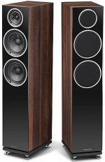
I got a Wharfedale Diamond 230 from a fiend for crossover upgrade...
It has a low cost crossover with iron core inductors and electrolytic capacitors bypassed with cheap polyester film caps. It measures good... probably, but sounds relatively bad...
I measured the inductors with LCR meter and rebuilt the new crossover with Miflex polypropylene capacitors, Visaton and Ohmite audio resistors, and Visaton air core inductors.
The new crossover parts costs about half of original speaker price! (~180 Euro)
Part list:
Capacitor MKP13-22U/400 MIFLEX 2 pcs
Capacitor MKP13-4.7U/400 MIFLEX 2 pcs
Capacitor MKP13-1U/400 MIFLEX 2 pcs
Capacitor KFPM01-0.1U/600 MIFLEX 4 pcs
(copper foil bypass cap for tweeter)
Resistor MOX-1.5R/10W-VS VISATON 2 pcs
Resistor MOX-10R/10W-VS VISATON 2 pcs
Resistor AG10-2.7R-5% OHMITE 2 pcs
Inductor SP-0.68MH48-VS VISATON 2 pcs
Inductor SP-1.5MH58-VS VISATON 2 pcs
Capacitor MKP13-27U/400 MIFLEX 2 pcs
The original inductors are 0.61mH and 1.3mH so I modified the inductors to match the original value.
See before and after pictures:
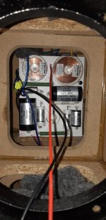
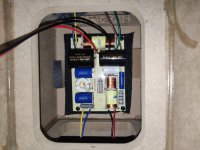
Original crossover:

New crossover:

It sounds completely different from original, with more detail, precise treble, better midrange and faster bass...
I got a Wharfedale Diamond 230 from a fiend for crossover upgrade...
It has a low cost crossover with iron core inductors and electrolytic capacitors bypassed with cheap polyester film caps. It measures good... probably, but sounds relatively bad...
I measured the inductors with LCR meter and rebuilt the new crossover with Miflex polypropylene capacitors, Visaton and Ohmite audio resistors, and Visaton air core inductors.
The new crossover parts costs about half of original speaker price! (~180 Euro)
Part list:
Capacitor MKP13-22U/400 MIFLEX 2 pcs
Capacitor MKP13-4.7U/400 MIFLEX 2 pcs
Capacitor MKP13-1U/400 MIFLEX 2 pcs
Capacitor KFPM01-0.1U/600 MIFLEX 4 pcs
(copper foil bypass cap for tweeter)
Resistor MOX-1.5R/10W-VS VISATON 2 pcs
Resistor MOX-10R/10W-VS VISATON 2 pcs
Resistor AG10-2.7R-5% OHMITE 2 pcs
Inductor SP-0.68MH48-VS VISATON 2 pcs
Inductor SP-1.5MH58-VS VISATON 2 pcs
Capacitor MKP13-27U/400 MIFLEX 2 pcs
The original inductors are 0.61mH and 1.3mH so I modified the inductors to match the original value.
See before and after pictures:
Original crossover:
New crossover:
It sounds completely different from original, with more detail, precise treble, better midrange and faster bass...
Attachments
Hello.
I have in plan to do this upgrade to my Diamond 230, but I have some questions, because I want to understand what you did there :
1. where are 16uF and 3.3uF capacitors from bass? I don't see them on the spare parts list, nor in the new crossover. What happend to them?
I can only suppose you have replaced them with a 22uF, but 19.3uF is way less than 22uF, you are modifyig the cutting point of the LPF. I saw you have adjusted inductors value, to match the original value, but didn't do this with the capacitors. Is there any reason for this?
2. did you replace 22uF + 4.7uF from tweeter with a 27uF?
3. Why did you add those 0.1uF capacitors?
4. I see you also modified the resistor values (1.5 instead of 1.8, and 2.7 instead of 3.3). Is there any reason for this?
Waiting for your reply.
Thank you!
Hello,Hello.
I have in plan to do this upgrade to my Diamond 230, but I have some questions, because I want to understand what you did there :
1. where are 16uF and 3.3uF capacitors from bass? I don't see them on the spare parts list, nor in the new crossover. What happend to them?
I can only suppose you have replaced them with a 22uF, but 19.3uF is way less than 22uF, you are modifyig the cutting point of the LPF. I saw you have adjusted inductors value, to match the original value, but didn't do this with the capacitors. Is there any reason for this?
2. did you replace 22uF + 4.7uF from tweeter with a 27uF?
3. Why did you add those 0.1uF capacitors?
4. I see you also modified the resistor values (1.5 instead of 1.8, and 2.7 instead of 3.3). Is there any reason for this?
Waiting for your reply.
Thank you!
1. I combined the 16 and 3.3uF from the woofer and the closest match was 22uF but it cuts a bit more high frequency from the woofer...
2. In the tweeter section I replaced the two capacitors with one 27uF and bypassed both tweeter caps with a copper foil 0.1uF to get a more detailed treble.
3. Bypass is not mandatory it only helps a little to speed up the big capacitor.
4. I put smaller resistor on the tweeter to get a little more upper sound but it's a personal preference only. The 2.7 was the closest value available that time so you can use original values.
Have a nice day!
Don't take this too hard, but without a before and after schematic of the crossover, it is impossible to assess whether what you have done actually makes any difference at all!
I also generally like to know the impedance and size and nature (Paper, metal, polycone) of the drivers. You can usually then guess what sort of circuit might work within all the possible variations.
And anyone hoping for some practical insight for a project is otherwise clueless.
Having seen many, so-called upgrades, and a recent one on the Wharfedale Diamond 11.1 springs to mind, I found that most of the changes did absolutely nothing or near-nothing in electrical terms when simulated.
Usually the main event is an adjustment to tweeter level. Which might suit your taste.
I can see how air-core coils might work (and measureably) slightly beter than ferrites, but the rest is just unknown.
Hello,
1. I combined the 16 and 3.3uF from the woofer and the closest match was 22uF but it cuts a bit more high frequency from the woofer...
2. In the tweeter section I replaced the two capacitors with one 27uF and bypassed both tweeter caps with a copper foil 0.1uF to get a more detailed treble.
3. Bypass is not mandatory it only helps a little to speed up the big capacitor.
4. I put smaller resistor on the tweeter to get a little more upper sound but it's a personal preference only. The 2.7 was the closest value available that time so you can use original values.
Have a nice day!
Hello,
1. Replacing 19.3uF with a 22uF can create a "big gap" between LPF and BPF (for the low-mid), that will result in some missing frequencies, or attenuated arround the cutting point. I wouldn't go that much with the new values.
2. Same idea for 27uF (+0.1uF) instead of initial 22uF+4.7uF. Of course the difference is small and there are +/-5% tolerances on the capacitors, so this new value is in the limits, but still wouldn't change the initial values. More than this, on the tweeter there is a 3rd order filter with 18dB attenuation/octave, that requires more attention to the design.
3. Not sure if that "bypass" does something more than adding extra capacitance.
4. Ok, true 🙂
Typical mistake which is made too often - replacing perfectly good iron-core inductor (for the woofer) with double (or triple) resistance air-core inductor (Visaton SP-1.5MH58-VS)!It has a low cost crossover with iron core inductors and electrolytic capacitors bypassed with cheap polyester film caps. It measures good... probably, but sounds relatively bad...
The new crossover parts ...
Inductor SP-1.5MH58-VS VISATON 2 pcs
The original inductors are 0.61mH and 1.3mH so I modified the inductors to match the original value.
It sounds completely different from original, with more detail, precise treble, better midrange and faster bass...
Faster bass? No way! Bigger resistance of the woofer inductor = bigger (equivalent) woofer Qts = slower bass.

If you mean my post for WD11.1, I think I explained it correctly.Having seen many, so-called upgrades, and a recent one on the Wharfedale Diamond 11.1 springs to mind, I found that most of the changes did absolutely nothing or near-nothing in electrical terms when simulated.
Usually the main event is an adjustment to tweeter level. Which might suit your taste.
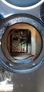
The tweeter level was too low, the bass reflex tube was clogged with damping material and the worst wiring with some poor steel connectors was there.
When you fix those things, you really hear a big difference.
If, for example, I made a completely new crossover with very high quality material, I would get a lot more, but that exceeds the price paid for those speakers, and there is not enough space in the box.
I've done it before, so I know for sure what the impact of quality components is. It is practically the same when measuring the frequency range, but the audible differences are not so small. I mean the case of replacing components with better ones, without any changes in the value of the components. In principle, this only pays off for higher quality and more expensive speakers.
Last edited:
Likely the sonic differences are solely due to the coil core changes. I am not a big believer in drastic changes from caps or resistors. Changes yes. Audible, maybe as I can't tell anyone else what they here, but iron to air can be quite audible and as the resistance most likely changed, it may effect the filter shape a little. I can believe a tiny difference in electro to a generic film, like a Dayton, but boutique caps? I think not.Hi,
I got a Wharfedale Diamond 230 from a fiend for crossover upgrade...
It has a low cost crossover with iron core inductors and electrolytic capacitors bypassed with cheap polyester film caps. It measures good... probably, but sounds relatively bad...
I measured the inductors with LCR meter and rebuilt the new crossover with Miflex polypropylene capacitors, Visaton and Ohmite audio resistors, and Visaton air core inductors.
The new crossover parts costs about half of original speaker price! (~180 Euro)
Part list:
Capacitor MKP13-22U/400 MIFLEX 2 pcs
Capacitor MKP13-4.7U/400 MIFLEX 2 pcs
Capacitor MKP13-1U/400 MIFLEX 2 pcs
Capacitor KFPM01-0.1U/600 MIFLEX 4 pcs
(copper foil bypass cap for tweeter)
Resistor MOX-1.5R/10W-VS VISATON 2 pcs
Resistor MOX-10R/10W-VS VISATON 2 pcs
Resistor AG10-2.7R-5% OHMITE 2 pcs
Inductor SP-0.68MH48-VS VISATON 2 pcs
Inductor SP-1.5MH58-VS VISATON 2 pcs
Capacitor MKP13-27U/400 MIFLEX 2 pcs
The original inductors are 0.61mH and 1.3mH so I modified the inductors to match the original value.
See before and after pictures:
Original crossover:
New crossover:
It sounds completely different from original, with more detail, precise treble, better midrange and faster bass...
Of course, your cost analysis shows why Wharfedale used cheap parts. I agree, basically good drivers and good designs, but they have always been a price point champ. ELAC is giving them some competition now I think.
Sound differences, more or less obvious are whatever you change, any passive component, wire, amount of damping material. Especially when you replace those cheapest parts from China that these days everyone puts in the speakers, even expensive ones. You can trust me. 
I can confirm that replacing resistors and electrolytic capacitors with MOX resistors (non-inductive) and MKP capacitors changes completely the sound of the speakers. I did that many times in the past, and it was not Placebo 🙂Sound differences, more or less obvious are whatever you change, any passive component, wire, amount of damping material. Especially when you replace those cheapest parts from China that these days everyone puts in the speakers, even expensive ones. You can trust me.
Never replaced inductors, as most of the times these are good (medium to high quality).
please avoid MOX resistors , sound really bad....
resistance air-core inductor MUST is better then before......
Caps in series with signal the better you can ...at last bypass
use 250v for good price ,motor run like ducati &co. for big ones
resistance air-core inductor MUST is better then before......
Caps in series with signal the better you can ...at last bypass
use 250v for good price ,motor run like ducati &co. for big ones
The problem is that most PP capacitors are much larger than the bip. el. caps, so in most cases they cannot fit on a PCB. Several times I made improvements to the speakers, amplifiers, preamplifiers, by installing the Wima MKS4 100VDC. They are metalized polyester film caps, but they are better than any electrolytic cap, and they are not too large. Bypass with a smaller PP cap is definitely recommended.
Motor run capacitors are polypropylene, high voltage (450VAC). They are good only for the bass section, a parallel cap that connects to GND as part of a filter or impedance correction. For the rest I would not recommend them, even with a bypass cap. Their large dimensions are a problem. There is no chance that they will be installed on existing PCB, only separately and connected by wires to PCB. They are also good as the first capacitor behind the tube rectifier, followed by inductance and then a larger capacitor (CLC filter).
MOX resistors can be good or bad, depending on the manufacturer. Lately I prefer Mundorf MR10 non inductive metal film, especially on the tweeter section. I usually get them at Audiophonics, France. What I practice from time to time is the parallel connection of several pieces of 2W metal film resistors (4-6).
Last edited:
first put the pcb out will sound better ...you know we do microphone with caps 😉 and better separation cpas and coils ...@aendre isn't good side by side 🙂
motor run isnt for series, is clear what I write .....btw I have 100u from claritycaps but dc-link are good too
mox sound bad from the good ones.....on tw we can use what we want not big power to play.....
motor run isnt for series, is clear what I write .....btw I have 100u from claritycaps but dc-link are good too
mox sound bad from the good ones.....on tw we can use what we want not big power to play.....
This time I was lucky 🙂 MKP caps fits perfect in the Wharfedale Diamond 230 crossover.The problem is that most PP capacitors are much larger than the bip. el. caps, so in most cases they cannot fit on a PCB.
MOX resistors can be good or bad, depending on the manufacturer.
I am using Mundorf MOX, I found them better than ceramic resistors you found in every cheap crossover.
Attachments
- Home
- Loudspeakers
- Multi-Way
- Wharfedale Diamond 230 crossover upgrade