This summer I ordered some of the clearance Vortex-15's from DIYSG. As a design exercise I worked up both a tapered TL and MLTL enclosure design using Hornresp.
Here is the hornresp input for the tapered TL. This was done using the t/s specs from here.

Stuffing modelled is ~2 lbs of polyfill over first 40" of the line.

Power response and impedance. Tuning is 39.5 Hz before stuffing, 35.7 Hz after.


Displacement is just a hair over xmax at 100w input.

Model tested with driver measurements posted by Brinkman in this thread. The raw response is a bit lumpier, but with stuffing it turns out nearly the same.
.png")
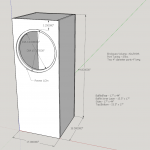
With things looking reasonably good here, I worked up a cabinet. Keeping the original design's 17" width, the dual requirements of reasonable tweeter height and box depth resulted in more wasted space than I would have preferred, but I couldn't think of another way to do it. Obviously this is a very large speaker - exterior is 17"w x 21"d x 55 1/4"h (not including the cosmetic double-baffle)

The MLTL has a similar floor footprint but is less imposing at 44" tall and with a slightly lower stuffed tuning of 30 Hz. I can share that one too if it's of interest to folks. I'm still not sure which I'm going to build, and I've not listed to either an MLTL or TL design before.
Here is the hornresp input for the tapered TL. This was done using the t/s specs from here.
Stuffing modelled is ~2 lbs of polyfill over first 40" of the line.
Power response and impedance. Tuning is 39.5 Hz before stuffing, 35.7 Hz after.
Displacement is just a hair over xmax at 100w input.
Model tested with driver measurements posted by Brinkman in this thread. The raw response is a bit lumpier, but with stuffing it turns out nearly the same.
With things looking reasonably good here, I worked up a cabinet. Keeping the original design's 17" width, the dual requirements of reasonable tweeter height and box depth resulted in more wasted space than I would have preferred, but I couldn't think of another way to do it. Obviously this is a very large speaker - exterior is 17"w x 21"d x 55 1/4"h (not including the cosmetic double-baffle)
The MLTL has a similar floor footprint but is less imposing at 44" tall and with a slightly lower stuffed tuning of 30 Hz. I can share that one too if it's of interest to folks. I'm still not sure which I'm going to build, and I've not listed to either an MLTL or TL design before.
Adding some missing info & dimensions to the cabinet drawing for the tapered TL.

I will try to post the MLTL to this thread later today.
I will try to post the MLTL to this thread later today.
I would love to see the MLTL. Nice work!
Me too, please! I've been checking every day since the last sale availability, and I just finished ordering a pair. I couldn't pass them up at half price. Thanks in advance. Glenn.
AFAIK, I bought the last pair of Vortex 15's. At least for now.
matt996, when you say the 44" tall MLTL, do you mean the following original drawing of the cabinet for the Vortex 15 as drawn by Matt Grant shown below and also in this thread?
Vortex Speaker Kits | Page 6 | HiFiCircuit
matt996, when you say the 44" tall MLTL, do you mean the following original drawing of the cabinet for the Vortex 15 as drawn by Matt Grant shown below and also in this thread?
Vortex Speaker Kits | Page 6 | HiFiCircuit
Attachments
Nearly. I started with Matt Grant's test box dimensions but found from playing around in hornresp that the driver needed to be a bit lower to get better cancellation of the first unwanted harmonic.
Overall external dimensions ended up very similar at 17"w x 45"h x 18 1/4"d. Driver centre is 14 3/4" down from top, and two 4" dia x 5" ports with centres 6 3/4" above bottom.
So, not a whole lot different from the test box and I certainly don't claim that this is new or novel. I did this mainly to better understand what the cabinet was doing in terms of MLTL behavior.
Don’t know if this related thread is of interest:
DIY Sound Group Vortex 15 sealed cabinet. Am I close?
DIY Sound Group Vortex 15 sealed cabinet. Am I close?
MLTL
MLTL hornresp input using t/s specs as above.

Stuffing modelled is ~2 lbs of polyfill over first 30" of the line.

SPL response and impedance. Modelled tuning is 31.8 Hz before stuffing (black), 30.1 Hz after (red).


Displacement simulates at a bit over xmax (6.5 mm) at 100w input. Port velocity is reasonable.


With the driver measurements posted by Brinkman, it loses a bit of output and the raw response isn't as smooth, but with the stuffing I think it still looks pretty good.
.png")
As I said I was not trying to break new ground here, just trying to better understand what was going on. The box is very similar dimension-wise to Matt Grant's test box, an inch taller and with the driver moved down a bit. Ports are the 4" Precision Ports with outer and inner flares only, for an effective 5" length.

MLTL hornresp input using t/s specs as above.
Stuffing modelled is ~2 lbs of polyfill over first 30" of the line.
SPL response and impedance. Modelled tuning is 31.8 Hz before stuffing (black), 30.1 Hz after (red).
Displacement simulates at a bit over xmax (6.5 mm) at 100w input. Port velocity is reasonable.
With the driver measurements posted by Brinkman, it loses a bit of output and the raw response isn't as smooth, but with the stuffing I think it still looks pretty good.
As I said I was not trying to break new ground here, just trying to better understand what was going on. The box is very similar dimension-wise to Matt Grant's test box, an inch taller and with the driver moved down a bit. Ports are the 4" Precision Ports with outer and inner flares only, for an effective 5" length.
I should have my Vortex 15 drivers soon. As well as clear some time to build them in the coming weeks. I am an experienced cnc guy and these files are not difficult to cut on my machine.
Which version should I build? I was leaning towards the original (tested) Matt Grant original but the modded MLTL version seems intriguing. The tapered TL is probably too big to fly here.
Which version should I build? I was leaning towards the original (tested) Matt Grant original but the modded MLTL version seems intriguing. The tapered TL is probably too big to fly here.
I'm asking myself the same thing except I'm between the MLTL and tapered TL.
The MLTL is close enough to the original size you could just cut a 2nd baffle to see if there's any audible difference/preference.
To the experienced ears here, is there a subjective difference between a TL vs. MLTL sound?
I'm also open to any suggestions regarding the hornresp models/dimensions/tuning..
I have all the parts now, and I am going to rework these old Sunn cabs for the time being to give the drivers a listen, and figure out the long term cabs. These are at 6.77 cubic feet before I redo the baffle and figure out bracing. 40×24×15 exterior dims. What calc could I use to see what the width does to bsc? The crossover was based on a 17 wide baffle. I'm contemplating the mltl, or the br tower that Matt used for the crossover and voicing, and visually going for Altec 604-8g Tannoy Arden look with 3 front round ports.
Attachments
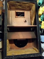

40×24×15 exterior dims. What calc could I use to see what the width does to bsc? The crossover was based on a 17 wide baffle.
I don't have experience in this area, which is why I kept to the original width in my cabinet drawings (plus my room demands keeping it as narrow as possible). My understanding is that baffle step frequency would shift a bit lower, while magnitude would be about the same. You could try the late Jeff Bagby's Baffle Diffraction and Boundary Simulator, available at Loudspeaker Design Software
Matt Grant commented on the BSC in a couple posts in the Vortex thread at HiFiCircuit, here:
There is a decent about of baffle step compensation built into the crossover of both the Vortex 12 and 15. The crossover does have a terminal block which when jumpered bypasses an inductor removing some of the baffle step but that is meant more for near wall placement of the speakers.
and here:
I'd try and keep the baffle width the same if you can. Adjustments there have impacts on the baffle step and diffraction frequencies which have been compensated for in the crossover with the stock baffle width. You could certainly make it 2" wider but know that the response in the lower midrange may just be slightly more uneven then stock, how much worse I can't say.
Knowing there was BSC built in, I expected to see an RL circuit in the crossover. But when the circuit was posted and there is no RL, I realized what Matt Grant meant when he said only some of the BSC could be removed. I’m a novice, but my understanding is that the crossover uses larger inductors than needed for the desired slope, with the extra inductance and resistance forming the BSC. So to change the BSC for a different width of baffle, you would need to change the inductor values and probably would end up redesigning the whole crossover to compensate.
Thank you, gentlemen. I think that I will try this cab out so that I can get them up and running, and just see how it sounds. I will just copy the dimensions of Matt's cabinet when I have the time and gather the materials. Glenn.
40×24×15 exterior dims. What calc could I use to see what the width does to bsc?
BSC docs: General Speaker Related Articles
30 Hz tapered TL
Just for fun I worked up a 30 Hz tuning for the tapered TL. This involved extending the lower rear panel up by another 10", and lowering the driver by 3.5", as well as some further optimizations to the bracing.

Hornresp inputs and stuffing, still ~2 lbs of polyfill:


1W SPL and impedance (black/red = before/after stuffing):


Modelled xmax is reached at 75W input:


Comparing the different models, the 30Hz TL edges the MLTL in sensitivity only slightly, about +1.3 dB near tuning. 35Hz-tuned TL is not suprisingly the most sensitive, but again not by all that much.

Based on all of this, I think the MLTL is going to be the winner for my build. Not all that much was gained for the additional size and build complexity of the tapered TLs I've shown here.
Just for fun I worked up a 30 Hz tuning for the tapered TL. This involved extending the lower rear panel up by another 10", and lowering the driver by 3.5", as well as some further optimizations to the bracing.
Hornresp inputs and stuffing, still ~2 lbs of polyfill:
1W SPL and impedance (black/red = before/after stuffing):
Modelled xmax is reached at 75W input:
Comparing the different models, the 30Hz TL edges the MLTL in sensitivity only slightly, about +1.3 dB near tuning. 35Hz-tuned TL is not suprisingly the most sensitive, but again not by all that much.
Based on all of this, I think the MLTL is going to be the winner for my build. Not all that much was gained for the additional size and build complexity of the tapered TLs I've shown here.

Looks like GM updated the other thread: https://www.diyaudio.com/community/...cabinet-am-i-close.375900/page-2#post-6817395
- Home
- Loudspeakers
- Multi-Way
- Tapered TL for DIYSG Vortex-15 (Denovo Hyperlite CX15-8)