I have some Aa tubes that will be used as a driver in my new amp Aa drives 50 monoblocks.
Per the attached Aa spec sheet, typical operating values: 3mA, 220V, -2V
Would like your thoughts on the following 2 alternatives for Aa operating values:
Option A
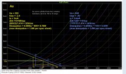
Ua = 240
bias = -3
Ia = 3.4mA
225-115=110Vpp
(110V/2)/1.414 = 39Vrms
Dissipation = 0.0086a * 110V= 0.95W = 63% max
(max dissipation = 1.5W per spec sheet)
Option B
Ua = 220
bias = -2.4
Ia = 3mA
205-115=90Vpp
(105V/2)/1.414 = 32Vrms
Dissipation = 0.0085a * 90V= 0.76W = 50% max
(max dissipation = 1.5W per spec sheet)
Not sure if this is enough to swing / drive the Type 50 output tube.
Also, I have a 4Vac filament tap. The Aa spec sheet calls for 3.8V. Do you foresee any issues using 4V instead of 3.8? I will try AC as I like the sound of AC, but if hum becomes an issue, then I will go to a regulated 3.8Vdc.
Note: The attached Aa curves are courtesy Intact Audio, Dave Slagle.
Thanks
Per the attached Aa spec sheet, typical operating values: 3mA, 220V, -2V
Would like your thoughts on the following 2 alternatives for Aa operating values:
Option A
Ua = 240
bias = -3
Ia = 3.4mA
225-115=110Vpp
(110V/2)/1.414 = 39Vrms
Dissipation = 0.0086a * 110V= 0.95W = 63% max
(max dissipation = 1.5W per spec sheet)
Option B
Ua = 220
bias = -2.4
Ia = 3mA
205-115=90Vpp
(105V/2)/1.414 = 32Vrms
Dissipation = 0.0085a * 90V= 0.76W = 50% max
(max dissipation = 1.5W per spec sheet)
Not sure if this is enough to swing / drive the Type 50 output tube.
Also, I have a 4Vac filament tap. The Aa spec sheet calls for 3.8V. Do you foresee any issues using 4V instead of 3.8? I will try AC as I like the sound of AC, but if hum becomes an issue, then I will go to a regulated 3.8Vdc.
Note: The attached Aa curves are courtesy Intact Audio, Dave Slagle.
Thanks
Attachments
Last edited by a moderator:
Are these loadlines for anode resistors of about 70K6 (option A) and about 73K3 (option B)?
I don't understand the calculation of the dissipation. I think that the currents should be 0.00086 (option A) and 0.00085 (option B). The voltage should be the anode voltage minus the voltage drop over the cathode resistor, so 177 - 3 = 174 V (option A) and 165 - 2.4 = 162.6 V. This would give a dissipation of 0.15 W (option A) and 0,14 W (option B).
I would feed the filaments with 3.8 V like they are supposed to.
My bad: I changed the 0.0085mA to 8.5mA. Now the calculations should be correct, indicating 0.95W and 0.76W, options A and B respectively. This seems very low given the 1.5W maximum.
Bartola® Valves
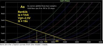
I found that 2V/160V was very good in terms of keeping the distortion profile to minimum.
Aa tube – Bartola(R) Valves
I found that 2V/160V was very good in terms of keeping the distortion profile to minimum.
Aa tube – Bartola(R) Valves
The tube is working at 170V and 0,85mA giving a dissipation of 170.0,85=145mW.My bad: I changed the 0.0085mA to 8.5mA. Now the calculations should be correct, indicating 0.95W and 0.76W, options A and B respectively. This seems very low given the 1.5W maximum.
Why that anode resistor of 70k ? Pick a "normal" value like 82k.
With a supply voltage of 250V you get this.
Mona
Attachments
Cagomat - I intend on using the Aa as a driver tube. The output tube will be a Type 50.
The typical #50 tube needs 150-160Vpp swing on the grid.
If you use Aa as driver, the headroom would be marginal, or insufficient.
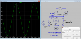
Use CCS /gyrator 2.75Ma or a choke will give 155Vp-p @2.5V bias
Attachments
Last edited:
Type #50 is a bit problematic tube, requires maximum 10k grid resistance: typically IT coupled driver or SF.
Type 50 Tube Amp
Type 50 Tube Amp
AA is a good preamp tube, but I would use this tube as driver
Not as driver!!! Why not RS241
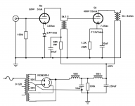
Here is the schematic so far. I adjusted the Rdropper to 68K 5W (common value) which give 226V Ua for the Aa.
Cagomat - Why not RS241? It only has a mu=17. The Aa = 30. If the RS241 is used instead of the Aa, then a 1:2 or 1:3 input transformer would be needed. The benefit of using the RS241 is no Rdropper is required.
Cagomat - Why not RS241? It only has a mu=17. The Aa = 30. If the RS241 is used instead of the Aa, then a 1:2 or 1:3 input transformer would be needed. The benefit of using the RS241 is no Rdropper is required.
Attachments
- Home
- Amplifiers
- Tubes / Valves
- Aa driver operating point