Up until now I always built my crossovers by using modeling software and FRD and ZMA files provided by the manufacturer (or I traced graphs if not provided). Recently I bought a measurement mic, the Dayton iMM-6 (the TRRS thing). I started a cheap project to get to know the process, a small 2-way based on the Dayton TCP115-4 midbass and ND25FA-4 tweeter.
First I imported the drivers' provided FRD files in VituixCad and generated versions with baffle step and diffraction taken into account (based on baffle dimensions and driver placement).
Next I did driver measurements. I assumed the responses would look a lot like the provided FRDs (with step and diffraction effects). But they were far off.
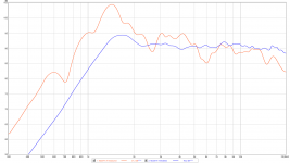
Below is the measured (gated) and modeled unfiltered response of the tweeter. The midbass driver did a bit better, but still far off the provided FRD.
Any idea why? Would it help to use a different mic, like a UMIK-1 or something? Or do you think the measurement is correct, and the provided FRD is just way off?
First I imported the drivers' provided FRD files in VituixCad and generated versions with baffle step and diffraction taken into account (based on baffle dimensions and driver placement).
Next I did driver measurements. I assumed the responses would look a lot like the provided FRDs (with step and diffraction effects). But they were far off.
Below is the measured (gated) and modeled unfiltered response of the tweeter. The midbass driver did a bit better, but still far off the provided FRD.
Any idea why? Would it help to use a different mic, like a UMIK-1 or something? Or do you think the measurement is correct, and the provided FRD is just way off?
Attachments
The first reflection was at 4.6ms, which was applied as the gate. So room acoustics shouldn’t have any effect.
The IMM6 plugs into your phone, yes? If you are holding the phone when you make a measurement, the phone, your hand, your person will all create reflections within the 4.6 ms window. To get a good high frequency response measurement, you will need a good microphone stand.
Some more clarification...
In general, you want your first reflection to be from the floor. Let's assume for instance that the floor is 35 inches from the driver being tested, you want a 35 inch radius sphere around the speaker to be clear of any reflective surface. You want a 35 inch radius cylinder of clear space between the speaker and the microphone. You want another 35 inch radius sphere around the microphone to be clear of any reflective surface.
This is worth reading:
Loudspeaker Measurements
j.
1) welcome to the Real World.I bought a measurement mic, the Dayton iMM-6 (the TRRS thing) ...... Dayton TCP115-4 midbass and ND25FA-4 tweeter.
...... Next I did driver measurements. I assumed the responses would look a lot like the provided FRDs (with step and diffraction effects). But they were far off.
Below is the measured (gated) and modeled unfiltered response of the tweeter. The midbass driver did a bit better, but still far off the provided FRD.
Any idea why? Would it help to use a different mic, like a UMIK-1 or something? Or do you think the measurement is correct, and the provided FRD is just way off?
Measuring beats guessing 1000:1 and I congratulate you for taking the deep plunge.
Now get ready to trust your own measurements and not what you read.
2) they are not "horrible" at all, at least compared to other real world measurements, nor I see there problems attributable to reflections, etc; of course having the actual microphone capsule at the end of a longish pencil type boom, say 15 to 25 cm long would make it a little more independent from surroundings, but again, I see nothing gross in your curves.
3) in fact your measurements are incredibly close 😱
Both show:
* tweeter resonance, supplied 1600Hz vs measured 1400Hz|(or so), you call that *wrong"? 😕
* peak has somewhat higher Q.
Again, same thing.
Both are well within production tolerances, easily attributable to Tweeter assembler using a larger than usual drop of adhesive, or that particular batch of paper or spider used being slightly more rigid than usual, no big thing.
* response slopes downward a little faster than expected.
I can easily attribute that to being slightly off axis; besides at such high frequencies and short wavelengths , a few mm change in mic position causes big frequency response changes, we also have lobing, etc.
Or it plain slides downward that way, it´s not a deal breaker considering tweeter price, but again, easily caused by mic position.
If anything, "reflections" may be indicated by roughly octave spaced broad notches at 2600 Hz and 5kHz .... they might also show some slightly undamped membrane resonance OR even some resonance between actual dome and tweeter mounting ring/fame.
Measure others and you will probably find similar "horribleness" 😉
Want Roger Corman horror film level curves?
You are seeing a very averaged out (by software) response; if yours allows it, try "not averaged/raw" response, instead of 1/3 - 1/6 - 1/12 octave, get the real deal.
You will faint

Last edited:
The IMM6 plugs into your phone, yes? If you are holding the phone when you make a measurement, the phone, your hand, your person will all create reflections within the 4.6 ms window. To get a good high frequency response measurement, you will need a good microphone stand.
Well, it plugs into my surface tablet (rew running on Windows). It’s supported by an aluminum folding ladder. Not ideal, but it could be worse. The speaker sits on the edge of a table, with the tweeter at around 125cm (close to 50”) high, halfway between the floor and the ceiling. The floor and ceiling are the closest reflective surfaces (apart from smaller surfaces like the ladder).
Last edited:
Well, it plugs into my surface tablet (rew running on Windows). It’s supported by an aluminum folding ladder. Not ideal, but it could be worse. The speaker sits on the edge of a table, with the tweeter at around 125cm (close to 50”) high, halfway between the floor and the ceiling. The floor and ceiling are the closest reflective surfaces (apart from smaller surfaces like the ladder).
Well, there may be enough sound from the drivers wrapping around the speaker that the table itself is affecting the measurements.
If you can, try using a speaker stand instead.
As JMFahey said, your measurements are not horrible. You have what appears to be a cancellation null at 2.5k and at 6k. The ladder, the taple top, it could all be effecting it.
Most driver measurements are done on a IEC baffle or in a cabinet large enough that edge diffraction is not going to be an issue within the measurement range. A cabinet or baffle with hard edges will exacerbate this effect to the point that it will create quite large ripples in the response. Place that driver on a big flat baffle and you should see something similar to the response measured by the manufacturer.
The peak at 1400Hz and the dip at 2800Hz is a pretty good indicator.
What is your baffle size, or are you measuring free-air?
The peak at 1400Hz and the dip at 2800Hz is a pretty good indicator.
What is your baffle size, or are you measuring free-air?
Last edited:
Okay, thanks everyone for the responses. I'll make sure to get a proper mic plus stands for the speaker and mic.
Any suggestions on the mic? The UMIK seems popular, but a while ago I read a post saying you really need a XLR one. The reason why eluded me, if there is a good reason why to get one over the other please let me know.
Any suggestions on the mic? The UMIK seems popular, but a while ago I read a post saying you really need a XLR one. The reason why eluded me, if there is a good reason why to get one over the other please let me know.
Not 100% sure but it might be because a XLR version can be used with a loop back on the other channel for measuring delay / timing properly , whereas with the usb version you have to use a reference timing speaker on the other channel for timing / delay measurements.
I have the USB version and get by ok fwiw.
Rob.
I have the USB version and get by ok fwiw.
Rob.
A good reason to go with an XLR mic would be if you want to do measurements at long distances, especially if you already own lots of XLR microphone cable, or would like to get into recording or PA work, where you will need lots of XLR.The UMIK seems popular, but a while ago I read a post saying you really need a XLR one. The reason why eluded me, if there is a good reason why to get one over the other please let me know.
XLR mics can use 100 meters or more cable with virtually no effect on audio, while USB Audio class 1.0 devices have cord length limits before data errors may occur.
That said, appears passive USB extension cords in the 6 to 10 meter range work OK with UMIK/REW.
A USB mic is perfectly fine for making frequency response measurements of a loudspeaker system, or a room. And it is fine for ordinary frequency response measurements of drivers along a single axis, such as on-axis. But if you want to capture the 3-dimensional radiation pattern of a driver and model that behavior with advanced simulation software, a USB mic is not the right tool.
A two-channel audio interface, combined with an XLR mic and software such as ARTA or REW, is capable of capturing both the frequency response and the phase / timing of the drivers. It can maintain a reference "starting point" in the time delay between drivers, and as the drivers are rotated off axis.
It is possible to design a very high performance speaker system using the measurements from a good calibrated USB mic. I have done it. But it takes experience and knowledge of accoustics and driver behavior to work around the USB mic limitations. With a 2 channel rig and modern simulation software (such as VituixCad2), there is a lot less guess work.
j.
ECM8000 (or two to compare) with a calibrator for absolute sensitivity:
Measurement Microphone Comparison — Jochen Schulz
to me it doesn't seem spending more until spending a lot more on B&K or earthworks and have everything else perfect as the differences are mostly in the HF.
If you want the best quality measurements you need to replace the ladder with a mic stand and ideally ditch the clip and use a long hollow pole to hold the mic. The easiest way I have found to hold the speaker is to incorporate two 35mm pole mounts and use a speaker stand. You can always remove and fill these when the design is completed.
The mic is probably absolutely fine. To me your measurement looks to be contaminated with some reflections. That's all.
Sorry Jim, I don't see the connection. The problem begins as soon as you want to use it for a crossover.hifijim said:And it is fine for ordinary frequency response measurements of drivers along a single axis, such as on-axis. But if you want to capture the 3-dimensional radiation pattern of a driver and model that behavior with advanced simulation software, a USB mic is not the right tool.
The problem begins as soon as you want to use it for a crossover
The challenge begins as soon as we want to use it for a crossover. It is a challenge that can be overcome. It is not ideal, it is not desirable, but it can work.
I just got 4 of these tcp115 in the mail today. I have exact same much to test as well. I also have some test boxes built from a few years ago to throw them in and do some measurements. It might take me a week, but I will post my results too so we can compare!
I just got 4 of these tcp115 in the mail today. I have exact same much to test as well. I also have some test boxes built from a few years ago to throw them in and do some measurements. It might take me a week, but I will post my results too so we can compare!
I'd be very interested in your measurements. What mic do you have? And do you also have the 4 ohm version of the TCP115? Please post your results in this thread or send me a PM.
Below you see my measurement. This is the nearfield response (port and driver combined) merged with far-field at 350Hz. So it would be interesting to compare results above this frequency.
Attachments

- Home
- Loudspeakers
- Multi-Way
- Why is my measurement so horrible?