Hi to all, finally some news regarding this project. I took up working on the amp and brought it back to life, after some extensive fault-searching. It is now up and running, repaired and mostly overhauled. I am waiting only for the three big capacitor cans (C904, 905, 906). Plus some final work 🙂
Thanks to @Mooly for walking me through the repair of a SONY TA-3650 last year, I would not have made this one without your advice. I am happy I could apply my learning this time! I also posted this message over at Audiokarma, where member rswojo scanned the service manual for me (thanks!)
This thread here is the sequel to an older one where I already announced the SONY: https://www.diyaudio.com/forums/sol...0-amp-2sd46-output-devices-2.html#post6665620
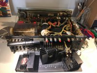
This amp is put together very tightly, so work was a bit difficult at times. It is tedious to unscrew a lot of stuff in order to access some parts: if you want to get to the output devices, you need to unscrew a horizontal bar on the upper side of the four individual heatsinks and unscrew each of them from below (two screws). Then you'll find that all the outputs are soldered into the sockets... Three (SONY 2SD88) of four were shot; the fourth (and intact) one was a SONY TX-183S. So somebody already had tried something. Obviously this transistor type (to my knowledge e.g. found in the SONY TA-3200F) seems to be more rugged. All 4 substituted with MJ15024.
Various resistors in both channels in various places were burned. Some small transistors had visibly exploded. The two unobtainable SONY drivers in each channel had miraculously withstood the damage. After pulling the outputs, replacing the burnt resistors, and a lot of testing of the main amp on a DBT (impossible to do this without) and comparing voltages, five other transistors were substituted.
The emitter resistors of one channel were open, which was invisible, so it took me a while to understand that this was why I could not get bias voltage there. After the repairs there was still intermittent distortion in the left channel, which went away when I poked at the bias pot. This also took some time; I found a nearly invisible broken trace close to the solder joint.
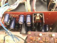
After the repair (better get that done first), I started the recap with mostly Panasonic FC which I like a lot. Slightly enhanced capacitance where possible: I went up from 220uF to 330uF (higher voltage) in the emitter feedback caps of the phono and pre amp, and from 470 to 680uF in the main amp for a lower f3. WIMA films for low value coupling and feedback caps.
As the power supply is intensely regulated (it is nearly the same circuit as the 6200F, missing one transistor, but for the rest very similar), I did not up the capacitances very much (for fear of making the transistors smoke). I put in 1800uF/35V FCs instead of 1000uF/10V at C807/808 in the power supply. The main filters will be those blue United Chemicon cans with 50mm diameter and 10000uF/100V which fit exactly in the space of the old ones. C904 will be substituted by a KEMET 1000uF/200V, which will also exactly fit the clamp (25mm).
I put in new dial lamps (8V fuse type). To access them the faceplate needs to be unscrewed, then you can also recap the pre amp which is fixed to the bass/treble pots. The stereo lamp is not fixed yet (stereo works), and I'll unscrew the dial glass again in order to clean the sides from old lacquer and put on new glass stain; the light is very dim and not very green. Maybe I'll then also change the Mylar input cap of the preamp into a bigger polypropylene which I left out for the moment. I'll also change the 4 pots in the main amp to new ones and will substitute the input cap C701/751 from a 0.22 green Mylar to a 0.47 WIMA MKP4, which I also very much like. So still some work ahead indeed.
Thanks to @Mooly for walking me through the repair of a SONY TA-3650 last year, I would not have made this one without your advice. I am happy I could apply my learning this time! I also posted this message over at Audiokarma, where member rswojo scanned the service manual for me (thanks!)
This thread here is the sequel to an older one where I already announced the SONY: https://www.diyaudio.com/forums/sol...0-amp-2sd46-output-devices-2.html#post6665620
This amp is put together very tightly, so work was a bit difficult at times. It is tedious to unscrew a lot of stuff in order to access some parts: if you want to get to the output devices, you need to unscrew a horizontal bar on the upper side of the four individual heatsinks and unscrew each of them from below (two screws). Then you'll find that all the outputs are soldered into the sockets... Three (SONY 2SD88) of four were shot; the fourth (and intact) one was a SONY TX-183S. So somebody already had tried something. Obviously this transistor type (to my knowledge e.g. found in the SONY TA-3200F) seems to be more rugged. All 4 substituted with MJ15024.
Various resistors in both channels in various places were burned. Some small transistors had visibly exploded. The two unobtainable SONY drivers in each channel had miraculously withstood the damage. After pulling the outputs, replacing the burnt resistors, and a lot of testing of the main amp on a DBT (impossible to do this without) and comparing voltages, five other transistors were substituted.
The emitter resistors of one channel were open, which was invisible, so it took me a while to understand that this was why I could not get bias voltage there. After the repairs there was still intermittent distortion in the left channel, which went away when I poked at the bias pot. This also took some time; I found a nearly invisible broken trace close to the solder joint.
After the repair (better get that done first), I started the recap with mostly Panasonic FC which I like a lot. Slightly enhanced capacitance where possible: I went up from 220uF to 330uF (higher voltage) in the emitter feedback caps of the phono and pre amp, and from 470 to 680uF in the main amp for a lower f3. WIMA films for low value coupling and feedback caps.
As the power supply is intensely regulated (it is nearly the same circuit as the 6200F, missing one transistor, but for the rest very similar), I did not up the capacitances very much (for fear of making the transistors smoke). I put in 1800uF/35V FCs instead of 1000uF/10V at C807/808 in the power supply. The main filters will be those blue United Chemicon cans with 50mm diameter and 10000uF/100V which fit exactly in the space of the old ones. C904 will be substituted by a KEMET 1000uF/200V, which will also exactly fit the clamp (25mm).
I put in new dial lamps (8V fuse type). To access them the faceplate needs to be unscrewed, then you can also recap the pre amp which is fixed to the bass/treble pots. The stereo lamp is not fixed yet (stereo works), and I'll unscrew the dial glass again in order to clean the sides from old lacquer and put on new glass stain; the light is very dim and not very green. Maybe I'll then also change the Mylar input cap of the preamp into a bigger polypropylene which I left out for the moment. I'll also change the 4 pots in the main amp to new ones and will substitute the input cap C701/751 from a 0.22 green Mylar to a 0.47 WIMA MKP4, which I also very much like. So still some work ahead indeed.
Attachments
Last edited:
 it sounds like you have done a good job and this one was quite challenging. They don't make them like this anymore.
Thank you for your reply, Mooly, and thanks for all I could learn in the first SONY job last year. Still remember the Curé's egg, every time I see a differential pair 🙂 It's also good to know and motivating that help is around the corner in case I get really stuck.
I am asking for your advice. STR6065 is fully functional. It has a strange sound and I don't know if it's normal. I set the currents according to the service manual. Now they are precisely set and checked after warming up even after 1 hour. I changed capacitors C905 and C906 and they have values of 6334uF and 6302uF. I also measured randomly selected others from each board, one piece at a time, and they also have values according to the service manual or the inscription on the capacitor. Usually a little more. About 10% more. Ucc I measured 2 x 49V on the capacitors. At full load it fluctuates between 46 and 49V. The sound is as if it is saturated with details and as if it is floating. I can't describe it. I am comparing it from Yamaha A1 and Saksa 85. Quadral Montan mk3 speakers. I also checked the sine wave using an oscilloscope at the output and they were nice and undistorted. 32Hz, 64Hz, 120Hz, 250Hz, 500Hz, 1K, 2k, 4k, 8k, 16kHz. Thank you in advance for your advice.
It is impossible to gauge anything like this really without actually hearing and comparing. If basic tests are OK then a good chance it is 'normal' as you put it. As well as spot frequency sine tests I would also check that the response is flat across the audio band and that square wave testing shows no abnormalities.
I would have suggested to ask @Mooly for advice on this, and now he is already here 🙂 . Thank you!
"strange sound" – as Mooly says, one needed to hear it to have an idea.
my experience with SONY receivers of this age is that – also stated in vague terms – due to aged caps they can sound very bassy (annoyingly so) or extremely trebly (with seemingly a lot of detail but somehow wrong). At this age your amp needs its caps replaced anyway. so that's what I would do, being optimistic that the sound balance will be restored to normal then.
You could also try a shot in the dark and change C702/752 first. These influence the sound much and could be dried out. Their specs are too low anyway and they limit bass. I went up to 470uF. Best would be Nichicon ES bipolar (the green ones) if they fit space-wise. You could even change those without pulling the power amp. could be worth a try.
Last edited:
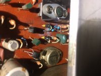
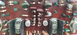
PS The photo of the restored power amp board I posted above shows two 4,7uF/50V WIMA film caps for C702/752. So you see where they sit. I changed those to 470uF/25V Panasonic FC afterwards.
Wrong, inherently wrong... 😉It is impossible to gauge anything like this really without actually hearing and comparing.
Take RMAA measurement and a lot of things may become clearer.
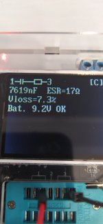
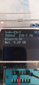
I don't have a microphone to measure RMAA. Maybe I'll buy one sometime. I currently need a desktop R2R ladder dac. I'm saving money for that. I measured these two capacitors and the result is in the photo. ESR? I replaced them with 100uF, 25V Nichicon. I only had these at home. The sound hasn't changed, it's still weird. I suggest my friend buy a set of capacitors and I will replace them all for him. Thanks again to all of you for your valuable advice. I will keep you posted on further developments.
Attachments
RMAA (software) uses soundcard, you do not need a microphone.I don't have a microphone to measure RMAA.
Dear all,
A couple of days ago, I received a SONY STR-6065 as a gift.
After opening the unit, I discovered that some components on the amplifier board were burnt. I didn't check the output transistors so far, but I'm pretty sure that they are defective, too.
Would you consider repairing this unit, or is it a hopeless case?
Thank you very much in advance for your advice.
Best,
Martin
Hi Martin, what a wildfire that must have been. It‘s not hopeless at all, only much work eventually. I‘ll chime back in later.
Hi, and thanks for your prompt reply.
I was hoping for your reply, as you are an expert on these old SONY Receivers.
I'm going to check the output transistors over the next couple of days, but I'm almost shure that they have been "killed".
I've been following some posts on the SONY STR-6065 and there appears to be a common understanding that the output transistors 2SD88 can be replaced with MJ15024. As far as I have understood, the diode SH-1S can be substituted with 1N4004. But so far, I don't really know what to do with the 2SC895.
Thank you for your most appreciated help in advance.
By the way, do you have a service manual that contains pages 45 and 46 (power supply) as the copy I downloaded from Hifi Engine is incomplete.
Hi @MartinJaeger I am sure you will get the receiver back into working order. Some skills will be needed but you can learn them as you go.
as to your questions:
do you have a dim bulb tester (DBT), so you can reduce the danger of smoking more components while you work on the machine? if not, it would be great to build one now. many threads on how to do that here or on the internet; in the most simple case put a 60W incandescent bulb in line with the life mains wire.
only one (the left) channel seems to be affected. that's already great. I used MJ15024 for the outputs as you suggest. the drivers Q708 (2SC895) and Q709 (2SA527) might need to be replaced by different packages (TO220 or TO126).
But first check what is defective, the drivers are rather rugged.
I'd start by a quick and dirty check of the left output devices with a digital multimeter (diode test mode) and if they read weird (probably) remove them and check them. same for the drivers. then all the burnt material needs to be removed (not everything that is blackened is burnt, some small transistors just got a lot of soot on them and you might save them). the PCB needs to be cleaned and inspected for burns and these restored (recreate burned tracks with thin copper wire or component leads).
when the defective left channel silicon is off the board you should be able to power on the receiver (if the right channel is ok). this should be done with a DBT.
I have only the track side of the power section in my version of the SM where I am now, I have the full version at home. I published the story over at audiokarma as well and member @rswojo sent me his full version of the manual (https://audiokarma.org/forums/index.php?threads/sony-str-6065-with-dead-main-amp-restoration.960847/).
Good start and good luck!
PS and don't forget to check the fuse... it is hidden somewhere behind where the mains cable comes into the enclosure. soldered in.
Hi @ eschenborn,
Thank you for the detailed response, which I greatly appreciate.
I do have a DBT and a variac to power up devices safely. As soon as I find the time, I will test the output transistors and start the repair of the amplifier board as described.
Would you desolder all the connecting cables on the amplifier board to be able to take the board completely out of the housing?
Once again thanks for your help.
Wonderful!
When I did the repair on the main amp of my 6065 I left the cables attached. If I were you I'd try so until handling it shows to be impossible 🙂
Lots of wires to de- and resolder (with lots of options to introduce errors).
I'd quickly test the drivers, too. They might be still ok. Just got some smoke 🙂 Mine were.
To me it looks like the plastic wrap of Q703 (the TO-220 transistor in the upper corner) somehow caught fire and created a lot of soot. but something below it must have started that burn.
I hopped that your advice would be to leave the cables attached 😉.
I do have a tester, so I will check all the drivers, including the one with the plastic wrap (Q703). You're perfectly right, Q703 or its plastic wrap could be the “source of destruction” (at least regarding the fire).
Is there a way you could provide me with the high-res scan of the manual of the STR-6065 at some point?
I don't have the manual where I am now and might not be able to access it for some weeks unfortunately. maybe ask the friendly audiokarma member (see post above)? Or someone else around here has it?
Q703 is not a driver, Q708 and 709 are. Q703 looks pretty finished from the photo.
I am curious what your findings will be.
Q703 is not a driver, Q708 and 709 are. Q703 looks pretty finished from the photo.
I am curious what your findings will be.
- Home
- Amplifiers
- Solid State
- SONY STR-6065 repair and restoration