Hi,
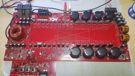
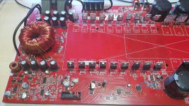
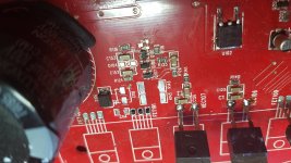
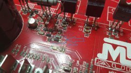
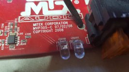
I repair MTX amplifier and accidentally shorted the power supply of the preamplifier board during measurements with a multimeter. As a result, the diode (most likely the zener) was damaged. Its designation on the PCB is D104. The PCB designation is MVP305-C 07/02/08
There is a similar diode on the other side and it seems to me to be the same as the damaged one, but I am definitely not. It seems to me that the circuits with two IRF540N mosfets can generate + - 15 voltages for operational amplifiers. One of them has been short-circuited and now I have + 45V on the TL074C operational amplifiers. 😡
Does anyone have this amplifier or its photos in high resolution or know what kind of diode it is?I would be grateful.
Attachments
Not yet, but when I get these two amps fixed, I'll write to you about it. I saw this trick in another thread, you suggested it.
I also learned a bit from your very helpful website (Basic Car Audio Electronics). Tomorrow I will deal with this measurement in hifonics and I will write in that thread, because I saw that you were the only one interested in it for which I thank you. There is a problem with one transformer. The secondary windings are short-circuited, but the bridge voltages are nevertheless good.
I also learned a bit from your very helpful website (Basic Car Audio Electronics). Tomorrow I will deal with this measurement in hifonics and I will write in that thread, because I saw that you were the only one interested in it for which I thank you. There is a problem with one transformer. The secondary windings are short-circuited, but the bridge voltages are nevertheless good.

The circuit you sent is almost identical to my 1500D. After a bit more careful analysis, I found a few damaged elements there, which I will order tomorrow.
After repairing the positive power section of the NE5532, there is a new problem. I replaced the NE5532 and 3120.
When I turn on the power supply set at 12.6V with a limit of 3A with the soldered NE5532, they start to heat up quickly and strongly. The IRF540 negative power NE5532 transistor also heats up very quickly.
The supply voltage drops to 8V and the current remains limited to 3A. It looks like a typical short circuit. When the NE5532 is desoldered, the voltage momentarily drops to 8V. As soon as the capacitors are charged, the voltage rises to 12.6V and the current drops to 0.6A.
@Perry Babin do you have any idea what could be wrong? I checked the whole negative section for NE5532 and everything is ok. I replaced the IRF540 even though it was operational and it did not help.
Are all of the heatsink mounted transistors tightly clamped to the heatsink?
Measuring directly across terminals 4 and 8, what is the DC voltage on the 5532s?
Measuring directly across terminals 4 and 8, what is the DC voltage on the 5532s?
I temporarily installed small heat sinks. After cleaning the large heat sink, I'll screw it on properly.
In one of the topics regarding 7801 you wrote (if I remember correctly) that the heating of the IRF540 is normal, because ne5532 is a load for the IRF.
The board with two TL074C and potentiometers is also provided by the IRF540. Turns out it's normal for this amp, but it's the first time I see the NE5532 at 70 degrees Celsius in operation.
As for the voltages from the power supply. Earlier I limited the current too much and that is why the amplifier would not start. After changing the current limit from 3A to 5A, the amplifier started.
I have sound at the output of the speaker terminals so there is some progress. Negative probe on pin no. 4 and positive probe on pin no. 8 - 31.4V on both NE5532.
Current limiting by a power supply causes a lot of problems. Current limiting by a 2 ohm resistor in series with the B+ line always worked better for me. Neither is perfect but the resistor was better.
The NE5532 that drives the input of the optocouplers runs hot. That's normal.
The NE5532 that drives the input of the optocouplers runs hot. That's normal.
Thanks for your help. Good advice with this resistor, and about the power supply. At that time, when I was buying it, I didn't know yet that I would repair car amplifiers.
It's only 0-30V and 0-5A power supply.
It's only 0-30V and 0-5A power supply.
If you're going to try the resistor, use a 100w cylindrical ceramic resistor. It can also double as a dummy load.
If you connect a 12v piezo buzzer across the resistor, it will give an audible indication of the current flow through the resistor so you will immediately be aware of a current change through the resistor.
If you connect a 12v piezo buzzer across the resistor, it will give an audible indication of the current flow through the resistor so you will immediately be aware of a current change through the resistor.
- Home
- General Interest
- Car Audio
- MTX TH-1500D