NOTE: This is NOT a help request but a suggestion to try using a ready made example in LTSpice. The example schematic is audioamp.asc.
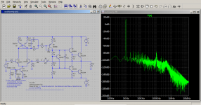
Note 2: For fun and curiosity I added a current mirror and two emitter resistors of value 22R and the distortion figure went down to 0.005%. Originally it was about 0.3%.
It is needless to state that current mirrors and current sources are a blessing!
Note 2: For fun and curiosity I added a current mirror and two emitter resistors of value 22R and the distortion figure went down to 0.005%. Originally it was about 0.3%.
It is needless to state that current mirrors and current sources are a blessing!
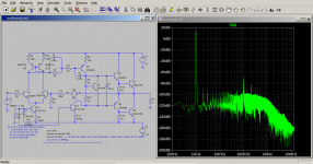
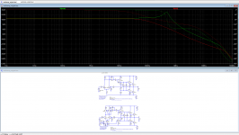
This is an attachment showing the phase and gain. The circuit is added a current mirror and a current source in the input stage. The second attachment shows the distortion.
Attachments

Ed, the phase margin is just a couple of degrees; this will be on the verge of oscillation if not oscillating in real life.
Jan
Jan
Adding a current source for the VAS and increasing C1 to 100pF further improved the distortion figure. The phase margin was also improved.
Attachments
Last edited:
Any reason for R4, R5, C1? They are driven from a high impedance source so may have little effect.
Adding a current source for the VAS and increasing C1 to 100pF further improved the distortion figure. The phase margin was also improved.
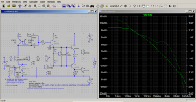
This makes it unstable, leaving it at 10pF gives the attached closed loop transfer function. At 20kHz the original circuit seems to preform slightly better but is much worse @1kHz.
Attachments
It seems to set a poleAny reason for R4, R5, C1? They are driven from a high impedance source so may have little effect.
I suggest you would be better to use input resistor degeneration to set the unity gain frequency ?
You also have high impedances on the input diff pair. The input 5k for example will reduce the frequency response of the input transistor and the same on the feedback side. That is probably why you did not get a good gain margin at first because of all the phase shifts (or poles if you prefer).
You also have a lower VAS current than the input diff pair. You need enough VAS current to drive the Miller capacitor.
I suggest you would be better to use input resistor degeneration to set the unity gain frequency ?
You also have high impedances on the input diff pair. The input 5k for example will reduce the frequency response of the input transistor and the same on the feedback side. That is probably why you did not get a good gain margin at first because of all the phase shifts (or poles if you prefer).
You also have a lower VAS current than the input diff pair. You need enough VAS current to drive the Miller capacitor.
Those are good suggestions.
This makes it unstable, leaving it at 10pF gives the attached closed loop transfer function. At 20kHz the original circuit seems to preform slightly better but is much worse @1kHz.
I agree; my previous post #7 is in error, I misread the phase curve. The phase margin of the new version is not 40deg, but -40deg!
Jan
LTSpice's ready made examples are intended only for educational purposes. This means, one, myself included, cannot expect them to be exhaustive in amplifier design. However, a learner has a big wealth of self-teaching resources without which learning would be harder.
My exercise consisted of changing and adding different components to try to improve the distortion figure. As current mirrors and current sources are used to improve amplifier circuits and analogue integrated circuits, such an exercise can be both entertaining and demonstrative of their effectiveness.
This particular ready made example is very easy to apply to other amplifier circuits and any other circuits which involve analogue signal processing.
I suggest you would be better to use input resistor degeneration to set the unity gain frequency ?
You also have high impedances on the input diff pair. The input 5k for example will reduce the frequency response of the input transistor and the same on the feedback side. That is probably why you did not get a good gain margin at first because of all the phase shifts (or poles if you prefer).
You also have a lower VAS current than the input diff pair. You need enough VAS current to drive the Miller capacitor.
How would one diagnose not enough current for the VAS? Slew rate?
The Miller capacitor used in the VAS is connected between the base and collector whose voltage undulates almost from rail to rail. If the rail voltage is V, with every cycle the Miller capacitor would need a charge of:
For a capacitor Q = C*V
A voltage swing of 2*V would require a charge of:
Q = C*2*V (C: Miller capacitor; V: rail voltage; two rails are assumed)
If the highest frequency is f, the average maximum charging current, I, would be:
I = 2*C*V*f
I has to be smaller than the VAS's constant current, otherwise, the Miller capacitor would not be charged quickly enough.
When the Miller capacitor discharges it supplies current to the VAS which should have enough standing current not to be disrupted by this extra current.
Last edited:
- Home
- Amplifiers
- Solid State
- Phase margin and gain on LTSpice.