Hi! I'm new to audio design, but decided to replicate a high-pass filter (Monacor DNH-185) to learn a bit.
I have a signal/function generator (UTG900E) and an oscilloscope (TDS1012B), but don't know how to go about using them to test which frequencies the filter is attenuating and passing.
Any help would be appreciated 🙂

I have a signal/function generator (UTG900E) and an oscilloscope (TDS1012B), but don't know how to go about using them to test which frequencies the filter is attenuating and passing.
Any help would be appreciated 🙂
Put a power amp between your signal generator and the input to this, and read Voltage across the speaker (watch levels or use an attenuator pad).
Be extremely careful with the volume level, it should be very low to avoid tweeter damage.
Without a mic, you have to measure the voltage across the driver, but that does not include
the driver's own characteristics. Maybe to start, just sub a resistor for the tweeter.
Without a mic, you have to measure the voltage across the driver, but that does not include
the driver's own characteristics. Maybe to start, just sub a resistor for the tweeter.
Last edited:
Put a power amp between your signal generator and the input to this, and read Voltage across the speaker (watch levels or use an attenuator pad).
What should I set the signal generator to? Sinus / square wave / etc? Then how many mV p-p (or mV RMS) would simulate the output of a passive bass guitar (normal playing, i know it would depend greatly of the tone played, how hard, etc)? Just to have a base line, and not blow my amp.
Then I'll feed this signal into the amp (the filter is for a bass guitar amp, Ampeg BA115HP), and make sure the amp is set to a low level.
What voltage levels should I see on the tweeter terminals (without the attenuator)? Just to know approx. what to look for? I guess I need either the tweeter or a resistor load, to now ruin the amp?
And another question, how sharp edge should I expect around the crossover frequency 5.5kHz? For example, full attenuation below 5.2kHz and none over say 5.8kHz?
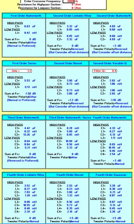
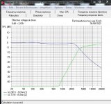
One look at that filter tells me it is an approx 5kHz Third Order Butterworth.
https://www.monacor.com/products/components/speaker-technology/crossover-networks-and-components-/dnh-185/?r=pdf
Can't think of an application for it! 😀
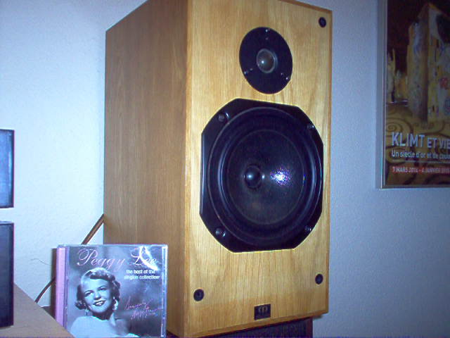
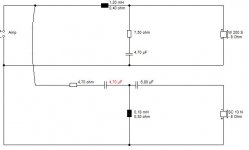
But with a bit of modding it might be a useful 3.5kHz tweeter crossover. Below images for an 8" speaker with 1" tweeter.
A signal generator and an oscilloscope wouldn't tell me much beyond the electrical response. And these days you use software like sweepgen to generate signals for your audio off your PC soundcard via a 3.5mm jack to phono.
Audio Tools - from David Taylor, Edinburgh
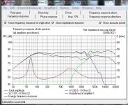
Far more useful is a competent simulator:
Software | Visaton
Filters can also be explored mathematically:
RF Tools | LC Filter Design Tool
All a bit of a learning curve, but the real deal. In practise most drivers can be considered as 6 ohms.
https://www.monacor.com/products/components/speaker-technology/crossover-networks-and-components-/dnh-185/?r=pdf
Can't think of an application for it! 😀
But with a bit of modding it might be a useful 3.5kHz tweeter crossover. Below images for an 8" speaker with 1" tweeter.
A signal generator and an oscilloscope wouldn't tell me much beyond the electrical response. And these days you use software like sweepgen to generate signals for your audio off your PC soundcard via a 3.5mm jack to phono.
Audio Tools - from David Taylor, Edinburgh
Far more useful is a competent simulator:
Software | Visaton
Filters can also be explored mathematically:
RF Tools | LC Filter Design Tool
All a bit of a learning curve, but the real deal. In practise most drivers can be considered as 6 ohms.
Attachments
Your intentions may need to be clarified. If you want to know the result of the filter, use the driver, not a resistor. If you want to mess around, use a resistor so you don't damage the tweeter. If you want to know the response in the end, use a microphone.
Start at 0 and work your way up to something useable.
It may not matter how loud, what are you testing again?
Sine. Sweep.Sinus / square wave / etc?
First time using an oscilloscope?how many mV
Start at 0 and work your way up to something useable.
Play it for real and look at the output.would simulate the output of a passive bass guitar
It may not matter how loud, what are you testing again?
Roughly 18dB/Octhow sharp edge should I expect around the crossover frequency
No, I'm a frequent user of oscilloscopes, but I meant how many mV (pp or rms) from the signal generator. Just a rough number not damage the input stage of the amp.
Most phono analog inputs are designed for maximum 100mV peak to peak at 50k input impedance. Most amplifier outputs have a much higher output around 5V peak to peak if you are caning it at high volume, and that is stable above 4 ohms.
Makes sense if you think an amplifier has a +/- 30V power rail.
I haven't used an oscilloscope in 40 years. Only really useful to amplifier designers. 😀
A top loudspeaker man might use equipment like Ryan at Impulse Audio:
Life S5 | Part 6: Final Measurements - YouTube
Too complicated and expensive for me. I am a simple soul. 😱
- Home
- Loudspeakers
- Multi-Way
- Testing a high-pass filter