No power, net labels need to match between voltage sources and supply rails.
VCC and VEE are not connected to the sources because they are incorrectly named VCC1 and VEE1.
VCC and VEE are not connected to the sources because they are incorrectly named VCC1 and VEE1.
The sources are named VCC1 and VEE1 and the nets are VCC and VEE. Transient analysis shows the correct rail voltages.
Last edited:
The nets and sources need to have the same net name or they are not connected, not sure why the DC operating point is correct, but change the net names to match and it should work.
I'm going to have another look and see what else I can find, went for a walk this afternoon.. 😀 I will also ask Mooly to have a look, he's our one of our resident LTSpice experts. This version isn't displaying correctly - trying to figure out what's up with that.
Cleaned up file, but there is definitely something wrong. I've asked for help. I broke it down into separate circuit blocks and it still doesn't work. I would probably substitute actual transistor models from the library for the generics although that should not prevent it from working.
In transient analysis it clips like crazy.
In transient analysis it clips like crazy.
Attachments
First of all, R16 and R21 limit the VAS current to about 0.14mA, which is not enough so you get clipping at about 2VPP. But this is not unrelated to the fundamental problem with this circuit, ie it is a symmetric IPS with no good way to define the VAS current, a classic design mistake. R16 and R21 are part of a failed attempt to resolve this problem. Changing these resistors to, say 47 Ohms can enable simulation but the results in a real circuit are unpredictable. The usual solution is to change the current mirrors Q6,Q7 and Q3,Q4 to a single resistor and add emitter degen resistors to the VAS Q9 and Q16. I think Bob Cordel has a partial solution that involves bleeding some current off the current mirrors, c /w VAS degen resistors. I played with other ways to fix this issue, mainly adjusting the offset of the two LTP separately, but the results are not better than other topologies so I would just forget it.
Now that you mention I vaguely remember that the issues you raised are a problem with this topology.
Cleaned up file, but there is definitely something wrong. I've asked for help. I broke it down into separate circuit blocks and it still doesn't work. I would probably substitute actual transistor models from the library for the generics although that should not prevent it from working.
In transient analysis it clips like crazy.
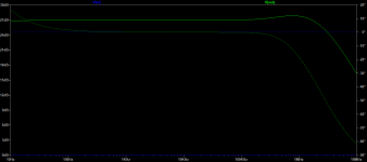
Yes I suspect it is the VA stage-I'm currently playing with it. The resistor should be changed to 4.7 vs 4.7k and then it works in the transient state but the transfer function is still -85dB.
Thank you, I had a typo on R16 and R21. Bringing it to 4.7 vs 4.7k gives reasonable transient performance but the transfer function is still nonsense. I will look at less complicated VA stages.First of all, R16 and R21 limit the VAS current to about 0.14mA, which is not enough so you get clipping at about 2VPP. But this is not unrelated to the fundamental problem with this circuit, ie it is a symmetric IPS with no good way to define the VAS current, a classic design mistake. R16 and R21 are part of a failed attempt to resolve this problem. Changing these resistors to, say 47 Ohms can enable simulation but the results in a real circuit are unpredictable. The usual solution is to change the current mirrors Q6,Q7 and Q3,Q4 to a single resistor and add emitter degen resistors to the VAS Q9 and Q16. I think Bob Cordel has a partial solution that involves bleeding some current off the current mirrors, c /w VAS degen resistors. I played with other ways to fix this issue, mainly adjusting the offset of the two LTP separately, but the results are not better than other topologies so I would just forget it.
Thank you! I have much to learnI don't have Bob's book but from what I've read, I think his solution looks something like this.
I don't have Bob's book but from what I've read, I think his solution looks something like this.
Mine does too in fact, but the AC analysis still does not work. (Transient analysis does work puzzlingly.)
this is an error in slone's book - this circuit doesn't reliably work as drawn; the current mirrors in the diff amp prevent defined voltages in the VAS.
this has been commented on in other threads on this site.
if you are determined to use current mirrors in the diff stages, you'll need to add some circuitry to define the operating points. I think Bob Cordell and Syn08 have posted changes that result in working circuits.
good luck!
this has been commented on in other threads on this site.
if you are determined to use current mirrors in the diff stages, you'll need to add some circuitry to define the operating points. I think Bob Cordell and Syn08 have posted changes that result in working circuits.
good luck!
The balanced class A circuit in his book is giving me issues. I replicated it in LT Spice and it flat out doesn't work. Can someone please take a look and advise?
- Home
- Amplifiers
- Solid State
- Issues replicating a class A circuit from Randy Slone's Book